• How to Polish Plastic Eyeglass Frames Without Whitening, Scratches, or Deformation
    How to Polish Plastic Eyeglass Frames Without Whitening, Scratches, or Deformation May 14 , 2026
    .jtj-article { max-width: 980px; margin: 0 auto; color: #1f2933; font-family: Arial, Helvetica, sans-serif; font-size: 16px; line-height: 1.72; } .jtj-article * { box-sizing: border-box; } .jtj-article h1, .jtj-article h2, .jtj-article h3 { color: #12212f; line-height: 1.28; margin: 0 0 14px; } .jtj-article h1 { font-size: 34px; margin-bottom: 18px; } .jtj-article h2 { font-size: 24px; margin-top: 36px; } .jtj-article h3 { font-size: 19px; margin-top: 24px; } .jtj-article p { margin: 0 0 16px; } .jtj-article a { color: #0b6fb3; text-decoration: underline; text-underline-offset: 3px; } .jtj-article .jtj-lead { font-size: 18px; color: #344454; margin-bottom: 22px; } .jtj-article .jtj-hero, .jtj-article .jtj-image { margin: 24px 0 28px; } .jtj-article img { width: 100%; height: auto; display: block; border-radius: 6px; } .jtj-article figcaption { color: #607080; font-size: 14px; margin-top: 8px; } .jtj-article .jtj-note, .jtj-article .jtj-cta { border-left: 4px solid #0b6fb3; background: #f2f7fb; padding: 18px 20px; margin: 24px 0; border-radius: 0 6px 6px 0; } .jtj-article .jtj-cta { background: #eef7f2; border-left-color: #25824b; } .jtj-article ul { padding-left: 22px; margin: 0 0 18px; } .jtj-article li { margin-bottom: 8px; } .jtj-article .jtj-table-wrap { overflow-x: auto; margin: 22px 0; border: 1px solid #d8e0e8; border-radius: 6px; } .jtj-article table { width: 100%; min-width: 760px; border-collapse: collapse; background: #fff; } .jtj-article th, .jtj-article td { padding: 12px 14px; border-bottom: 1px solid #e5ebf0; text-align: left; vertical-align: top; } .jtj-article th { background: #f5f8fa; color: #12212f; font-weight: 700; } .jtj-article .jtj-related { display: flex; flex-wrap: wrap; gap: 10px; margin: 18px 0 4px; } .jtj-article .jtj-related a { display: inline-block; border: 1px solid #c9d7e3; border-radius: 999px; padding: 8px 12px; text-decoration: none; background: #fff; color: #164d76; } @media (max-width: 768px) { .jtj-article { font-size: 15px; line-height: 1.68; } .jtj-article h1 { font-size: 27px; } .jtj-article h2 { font-size: 21px; } .jtj-article .jtj-lead { font-size: 16px; } .jtj-article .jtj-note, .jtj-article .jtj-cta { padding: 15px; } } How to Polish Plastic Eyeglass Frames Without Whitening, Scratches, or Deformation Plastic and acetate eyeglass frames are difficult to polish in batches because the surface must become bright and smooth without whitening, deep scratches, rounded corners, or heat deformation. A process that is too aggressive can damage the frame shape. A process that is too weak leaves mold marks, sanding marks, dull edges, or cloudy areas around the bridge and temples. This guide explains how to diagnose common polishing problems on plastic eyeglass frames and how to build a more stable finishing process for frame fronts, temples, corners, and visible outer surfaces. Quick answer: If plastic eyeglass frames turn white, keep scratches, or lose shape during polishing, check media hardness, processing time, heat buildup, part loading, and whether the process needs separate smoothing and final polishing stages. Plastic frames usually need gentler contact and better process control than metal hardware. Why Plastic Eyeglass Frames Are Easy to Damage Plastic frame materials such as acetate, PC, TR-type plastics, and other decorative plastics can look premium when polished correctly, but they are sensitive to heat, impact, and over-cutting. The surface may become cloudy or white if the polishing action is too dry, too hot, too rough, or too long. Eyeglass frames also have many difficult areas: the bridge, lens groove, hinge zone, temple connection, inner corners, and thin edge transitions. These areas can trap media, receive uneven contact, or become rounded before the large visible surface becomes bright. Start by Identifying the Defect Do not solve every plastic polishing problem by increasing time. First decide whether the defect is a cutting issue, a heat issue, a media issue, or a loading issue. Defect Likely Cause What to Check Recommended Adjustment White or cloudy surface Excessive friction, dry contact, or unsuitable media Media type, moisture, compound, cycle time Use gentler media and reduce heat or friction buildup Fine scratches remain Previous sanding marks too deep or media too coarse Initial surface preparation and media grade Add controlled smoothing before final polishing Frame corners become rounded Cycle time too long or contact too aggressive Corner radius, edge definition, processing time Shorten cutting stage and separate final polishing Frame shape changes or warps Heat, pressure, or excessive batch impact Machine motion, load size, drying temperature Reduce heat exposure and avoid heavy part-on-part contact Bridge or hinge areas remain dull Media cannot reach narrow or recessed areas Media size, lens groove, hinge geometry Test smaller or better-shaped media without causing lodging Use a Gentler Process Than Metal Deburring Plastic eyeglass frames should not be treated like stainless steel or die-cast parts. Heavy cutting media may remove material quickly, but it can also create haze, edge loss, or deformation. For plastic surfaces, the process should focus on controlled smoothing and gradual brightness improvement. Depending on the material and surface condition, plastic media, selected soft finishing media, or dry finishing media may be more suitable than aggressive cutting media. The final choice depends on frame material, sanding mark depth, corner requirements, and target gloss. Control Heat and Friction Heat is one of the biggest risks in plastic frame polishing. Even if the frame does not visibly melt, excess friction can soften the surface, create cloudy areas, or make sharp details look rounded. Dry polishing, long cycle time, and dense loading can all increase temperature. If whitening appears after the process, check whether the parts were overheated or rubbed too aggressively. A shorter process with better media selection is often safer than a long cycle with strong friction. Plastic frames need a controlled process that improves gloss while protecting corners, lens grooves, and thin frame sections. Prevent Part-on-Part Damage Eyeglass frames are light, thin, and easy to scratch. If too many frames are loaded together, they can rub or hit each other during finishing. This creates new marks that must be repaired manually. Loading ratio matters as much as media selection. The parts should be supported by enough media so frames do not stack, twist, or rub directly against each other. For some frame designs, a gentler machine motion or special fixture method may be needed. Choose the Machine by Frame Shape A standard vibratory finishing machine can work for many small plastic components, but eyeglass frames may require lower impact and better control. For delicate frames, a slower tumbling or dedicated plastic polishing process may reduce scratches and deformation. If the frames are long, thin, or easily tangled, the key question is not only machine capacity. You need to test whether the frames move freely, stay separated, and receive even contact around the bridge, temples, and lens grooves. Use Compound or Dry Media Carefully In wet processing, finishing compounds can help lubrication, cleaning, and surface protection. In dry finishing, the media must be clean and suitable for the plastic surface. Dirty or worn media can transfer residue and create uneven gloss. If the frame looks bright in some areas but hazy in others, check media cleanliness, compound residue, drying method, and whether narrow areas are trapping dust or slurry. When to Use a Two-Stage Process Many plastic eyeglass frames need at least two stages. One step removes sanding marks or mold marks. Another step improves gloss and surface uniformity. Trying to do both in one strong process often causes whitening or edge loss. Stage 1: controlled smoothing to remove visible sanding marks and surface unevenness. Stage 2: gentle polishing to improve gloss without overheating the frame. Final check: inspect bridge areas, corners, lens grooves, and temple connection points. Common Mistakes to Avoid Using metal deburring logic on plastic frames. Increasing cycle time until the surface turns white or edges lose definition. Ignoring heat buildup during dry or high-friction finishing. Loading too many frames together and creating scratches from part-on-part contact. Choosing media that cannot reach lens grooves or bridge corners. Skipping final inspection under consistent lighting. Related Solutions If you are improving plastic eyeglass frame polishing, these pages may help you compare suitable finishing media, compounds, and machine options: Plastic Media Dry Finishing Media Finishing Compounds Rotary Barrel Tumbling Machines Vibratory Finishing Machine Finishing Applications Need a Safer Polishing Process for Plastic Frames? Send us your frame material, photos, current surface condition, sanding mark depth, whitening problem, target gloss, and batch quantity. JINTAIJIN can help review whether your process needs different media, shorter cycle time, better loading control, or a two-stage polishing route. Contact our finishing team for plastic eyeglass frame polishing support
  • How to Finish Medical Instrument Parts Without Scratches, Residue, or Rounded Edges
    How to Finish Medical Instrument Parts Without Scratches, Residue, or Rounded Edges May 14 , 2026
    .jtj-article { max-width: 980px; margin: 0 auto; color: #1f2933; font-family: Arial, Helvetica, sans-serif; font-size: 16px; line-height: 1.72; } .jtj-article * { box-sizing: border-box; } .jtj-article h1, .jtj-article h2, .jtj-article h3 { color: #12212f; line-height: 1.28; margin: 0 0 14px; } .jtj-article h1 { font-size: 34px; margin-bottom: 18px; } .jtj-article h2 { font-size: 24px; margin-top: 36px; } .jtj-article h3 { font-size: 19px; margin-top: 24px; } .jtj-article p { margin: 0 0 16px; } .jtj-article a { color: #0b6fb3; text-decoration: underline; text-underline-offset: 3px; } .jtj-article .jtj-lead { font-size: 18px; color: #344454; margin-bottom: 22px; } .jtj-article .jtj-hero, .jtj-article .jtj-image { margin: 24px 0 28px; } .jtj-article img { width: 100%; height: auto; display: block; border-radius: 6px; } .jtj-article figcaption { color: #607080; font-size: 14px; margin-top: 8px; } .jtj-article .jtj-note, .jtj-article .jtj-cta { border-left: 4px solid #0b6fb3; background: #f2f7fb; padding: 18px 20px; margin: 24px 0; border-radius: 0 6px 6px 0; } .jtj-article .jtj-cta { background: #eef7f2; border-left-color: #25824b; } .jtj-article ul { padding-left: 22px; margin: 0 0 18px; } .jtj-article li { margin-bottom: 8px; } .jtj-article .jtj-table-wrap { overflow-x: auto; margin: 22px 0; border: 1px solid #d8e0e8; border-radius: 6px; } .jtj-article table { width: 100%; min-width: 760px; border-collapse: collapse; background: #fff; } .jtj-article th, .jtj-article td { padding: 12px 14px; border-bottom: 1px solid #e5ebf0; text-align: left; vertical-align: top; } .jtj-article th { background: #f5f8fa; color: #12212f; font-weight: 700; } .jtj-article .jtj-related { display: flex; flex-wrap: wrap; gap: 10px; margin: 18px 0 4px; } .jtj-article .jtj-related a { display: inline-block; border: 1px solid #c9d7e3; border-radius: 999px; padding: 8px 12px; text-decoration: none; background: #fff; color: #164d76; } @media (max-width: 768px) { .jtj-article { font-size: 15px; line-height: 1.68; } .jtj-article h1 { font-size: 27px; } .jtj-article h2 { font-size: 21px; } .jtj-article .jtj-lead { font-size: 16px; } .jtj-article .jtj-note, .jtj-article .jtj-cta { padding: 15px; } } How to Finish Medical Instrument Parts Without Scratches, Residue, or Rounded Edges Medical instrument parts and precision metal components often have strict surface requirements. The part must be clean, smooth, and consistent, but critical edges, holes, hinge areas, and contact surfaces cannot be over-rounded or damaged. A finishing process that works for general hardware may create scratches, residue, uneven texture, or excessive edge loss on these parts. This article explains how to diagnose common finishing defects on medical instrument parts and how to build a more controlled deburring, smoothing, and polishing process for precision components. Quick answer: For medical instrument parts, start with a controlled low-damage process. Choose media by part geometry, not only by material. Keep cutting action moderate, use clean compound and water flow, avoid overloading the batch, and inspect edges, holes, and contact surfaces after every test stage. Why Medical Instrument Parts Are Easy to Damage During Finishing Many medical instrument parts are made from stainless steel or other corrosion-resistant alloys. These materials can be strong, but the part geometry is often thin, curved, or precision-machined. Small changes to edges or surfaces can affect assembly, appearance, or inspection results. The main challenge is balance. The process must remove burrs, smooth machining marks, and improve the surface without creating new defects. If the media is too aggressive, edges become rounded. If the process is too mild, burrs and tool marks remain. Diagnose the Defect Before Changing the Process Do not treat every surface problem as a polishing problem. Scratches, cloudy surfaces, residue, and rounded edges come from different causes. The table below helps separate the issue before choosing media or changing cycle time. Defect Likely Cause What to Check Recommended Adjustment Fine scratches remain after finishing Media too coarse or previous tool marks too deep Initial roughness, media grade, process sequence Add a controlled smoothing step before final polishing Edges are rounded too much Cycle time too long or cutting action too strong Edge radius, media type, processing time Reduce cutting time and test gentler media Residue or gray film remains Dirty water, wrong compound, metal fines Water clarity, compound concentration, media cleanliness Improve rinsing and use suitable finishing compound Holes or hinge areas still have burrs Media cannot reach critical features Hole size, slot width, media shape Test media shape and size against actual geometry Surface differs from part to part Batch load is too high or parts shield each other Part-to-media ratio, nesting, loading density Reduce load and improve media support around parts Choose Media for the Critical Feature Media selection should start from the most sensitive area of the part. For medical instrument components, this may be a thin edge, hinge slot, contact surface, hole, or curved face. If the media cannot reach that area, burrs remain. If the media is too aggressive, the feature may lose definition. Ceramic media can be useful for controlled cutting and smoothing, but it must be selected carefully for precision parts. For more delicate surfaces, plastic media or a finer finishing step may reduce impact marks and over-cutting. Real sample comparison: precision parts need controlled surface improvement without losing edge definition or leaving residue. Control Batch Loading to Prevent Part-on-Part Marks Scratches and dents often come from part-on-part contact, not from the media alone. If parts are thin, curved, or have polished visible surfaces, a crowded batch can cause more rework than it saves. A vibratory finishing machine can process many precision parts efficiently, but the load ratio must be tested. There should be enough media to separate and support the parts during movement. For longer or fragile components, a tub vibrator or special loading method may provide better control. Use Compound and Rinsing to Avoid Residue Residue is a serious problem for precision parts because it can hide in holes, slots, or hinge areas. Finishing compounds help suspend metal fines, improve cleaning, control foam, and reduce staining. The compound should match the material and the required surface condition. If parts look acceptable when wet but show film after drying, check rinse quality, water cleanliness, compound concentration, and drying speed. For high-appearance parts, the cleaning and drying step should be treated as part of the finishing process, not an afterthought. When a Two-Stage Process Is Safer Precision parts often need more than one stage. One aggressive step may remove burrs quickly, but it may also round edges or leave a matte surface. A staged process gives better control. Stage 1: light deburring or smoothing to remove sharp edges and machining marks. Stage 2: finer finishing or polishing to improve texture and appearance. Final cleaning: rinse and dry parts quickly to prevent residue, water spots, or trapped contamination. Inspection: check holes, slots, edges, and contact surfaces under consistent lighting. Common Mistakes to Avoid Using strong cutting media to solve every burr problem. Extending cycle time until precision edges become rounded. Ignoring part-on-part contact in crowded batches. Choosing media without checking holes, hinge areas, and slots. Skipping rinse and drying control after wet finishing. Judging only the visible surface while missing residue in hidden areas. Related Solutions If you are developing a stable finishing process for medical instrument parts or other precision components, these pages may help you compare suitable machines, media, and compounds: Vibratory Finishing Machine Tub Vibrators Ceramic Media Plastic Media Finishing Compounds Industrial Dryers Need a Controlled Finishing Process for Precision Parts? Send us your part material, photos, drawing, burr locations, critical edges, surface requirement, and batch quantity. JINTAIJIN can help review whether your process needs different media, a staged finishing route, improved cleaning, or a more controlled machine setup. Contact our finishing team for precision part finishing support
  • How to Reduce Manual Deburring Work for Small Hardware Parts
    How to Reduce Manual Deburring Work for Small Hardware Parts May 11 , 2026
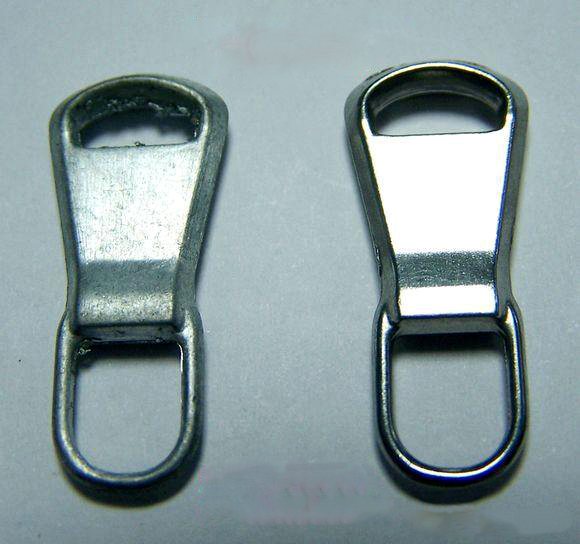
    .jtj-article { max-width: 980px; margin: 0 auto; color: #1f2933; font-family: Arial, Helvetica, sans-serif; font-size: 16px; line-height: 1.72; } .jtj-article * { box-sizing: border-box; } .jtj-article h1, .jtj-article h2, .jtj-article h3 { color: #12212f; line-height: 1.28; margin: 0 0 14px; } .jtj-article h1 { font-size: 34px; margin-bottom: 18px; } .jtj-article h2 { font-size: 24px; margin-top: 36px; } .jtj-article h3 { font-size: 19px; margin-top: 24px; } .jtj-article p { margin: 0 0 16px; } .jtj-article a { color: #0b6fb3; text-decoration: underline; text-underline-offset: 3px; } .jtj-article .jtj-lead { font-size: 18px; color: #344454; margin-bottom: 22px; } .jtj-article .jtj-hero, .jtj-article .jtj-image { margin: 24px 0 28px; } .jtj-article img { width: 100%; height: auto; display: block; border-radius: 6px; } .jtj-article figcaption { color: #607080; font-size: 14px; margin-top: 8px; } .jtj-article .jtj-note, .jtj-article .jtj-cta { border-left: 4px solid #0b6fb3; background: #f2f7fb; padding: 18px 20px; margin: 24px 0; border-radius: 0 6px 6px 0; } .jtj-article .jtj-cta { background: #eef7f2; border-left-color: #25824b; } .jtj-article ul { padding-left: 22px; margin: 0 0 18px; } .jtj-article li { margin-bottom: 8px; } .jtj-article .jtj-table-wrap { overflow-x: auto; margin: 22px 0; border: 1px solid #d8e0e8; border-radius: 6px; } .jtj-article table { width: 100%; min-width: 760px; border-collapse: collapse; background: #fff; } .jtj-article th, .jtj-article td { padding: 12px 14px; border-bottom: 1px solid #e5ebf0; text-align: left; vertical-align: top; } .jtj-article th { background: #f5f8fa; color: #12212f; font-weight: 700; } .jtj-article .jtj-related { display: flex; flex-wrap: wrap; gap: 10px; margin: 18px 0 4px; } .jtj-article .jtj-related a { display: inline-block; border: 1px solid #c9d7e3; border-radius: 999px; padding: 8px 12px; text-decoration: none; background: #fff; color: #164d76; } @media (max-width: 768px) { .jtj-article { font-size: 15px; line-height: 1.68; } .jtj-article h1 { font-size: 27px; } .jtj-article h2 { font-size: 21px; } .jtj-article .jtj-lead { font-size: 16px; } .jtj-article .jtj-note, .jtj-article .jtj-cta { padding: 15px; } } How to Reduce Manual Deburring Work for Small Hardware Parts Manual deburring is often the hidden cost in small hardware production. Operators may spend hours removing sharp edges, cleaning holes, touching up rough surfaces, and reworking parts that still do not look consistent. The problem is not always the operator. In many cases, the mass finishing process is not matched to the part shape, burr location, and final appearance requirement. Small hardware parts such as buckles, clips, zipper pulls, hooks, fasteners, stamped parts, and small die-cast fittings usually have holes, slots, thin edges, and visible surfaces. If the process is too weak, burrs remain. If it is too aggressive, edges become rounded, parts hit each other, or the surface becomes dull. The right process should reduce hand work without creating new defects. Quick answer: To reduce manual deburring, do not only increase tumbling time. First identify where the burrs remain, then adjust media size, media shape, part-to-media ratio, compound, cycle time, and separation method. For small hardware parts, the process must remove burrs in holes and edges while protecting visible surfaces from impact marks. Why Manual Deburring Remains After Tumbling If parts still need heavy hand work after tumbling, the finishing process is usually missing one of three things: enough contact at the burr location, suitable cutting strength, or stable part movement. Small hardware parts are especially sensitive because the burrs are often located in holes, stamped edges, hooks, narrow slots, or inside corners. A standard batch process may polish the exposed surface while leaving the problem area untouched. This is why a part can look better after finishing but still fail inspection because the edge is sharp or a hole still has a burr. Diagnose the Remaining Hand Work Before changing the machine or buying a new media, separate the hand work into categories. The correction depends on the specific defect. Remaining Problem Likely Cause What to Check Recommended Adjustment Burrs remain inside holes Media cannot reach or does not rotate through the hole edge Hole diameter, media size, media shape Test smaller or better-shaped media, but avoid media that can lodge Outer edges are clean but slots are still sharp Media bridges over narrow slots Slot width, media contact pattern, cycle time Use media geometry that can enter the slot without sticking Parts are deburred but surfaces are dented Part-on-part impact or media too heavy Batch load, part-to-media ratio, material softness Increase media support, reduce batch load, or use gentler media Finish is dull after burr removal Cutting stage is too aggressive for final appearance Media grade, compound, final surface requirement Add a finer finishing or polishing stage Manual sorting is slow after finishing Media lodging or poor separation Screen size, holes, slots, part openings Improve separation and avoid media close to feature dimensions Choose Media by Burr Location For small hardware parts, the media must be selected by the burr location, not only by the material. If the burr is on an outside edge, many media shapes may work. If the burr is inside a slot, hole, or hook, the wrong media may not touch the burr at all. Ceramic media can provide stronger cutting for harder burrs, stamped edges, and rough cast surfaces. Plastic media may be safer for softer alloys, decorative parts, or surfaces that are easy to dent. For many small hardware parts, a sample test should compare more than one media shape and size. Small hardware parts often need both edge control and surface improvement. A stable process should reduce hand work without damaging visible areas. Control Part-on-Part Contact Small parts can collide heavily when the batch load is too high or when there is not enough media between parts. This can create dents, scratches, bent edges, or inconsistent brightness. If operators need to hand-polish impact marks after tumbling, the process is not actually saving labor. A vibratory finishing machine is often suitable for batch hardware deburring, but the loading ratio must be controlled. Parts should move with the media, not crash into each other in a crowded bowl. Use Compound to Keep the Process Clean Finishing compounds help clean the surface, control foam, suspend metal fines, and improve lubrication. Without suitable compound, small parts may come out gray, sticky, or stained, creating extra cleaning or polishing work after deburring. If the process water becomes dirty quickly, or if parts need wiping after finishing, check compound concentration, water flow, media cleanliness, and whether the machine needs cleaning. Do Not Use Longer Time as the First Fix Longer cycle time may reduce some burrs, but it can also round functional edges, increase media wear, create part-on-part marks, and make the surface dull. If burrs remain only in specific areas, the issue is usually contact access, not total time. A better test method is to change one variable at a time: media shape, media size, part-to-media ratio, compound, or loading density. Record the result so the process can be repeated in production. When a Second Stage Is Worth It Some hardware parts cannot be finished well in one step. A first stage may be needed for burr removal, followed by a second stage for smoothing, brightening, or burnishing. This is especially useful when the customer requires both safe edges and a clean decorative surface. Stage 1: remove burrs and sharp edges with controlled cutting. Stage 2: improve surface uniformity or brightness with finer media or polishing media. Final check: inspect holes, slots, hook areas, and visible surfaces before approving batch production. Common Mistakes That Increase Manual Work Choosing media by material only, without checking where the burrs are located. Using media that is close to the hole or slot size, causing lodging and slow sorting. Overloading the machine and creating part-on-part damage. Trying to remove heavy burrs and create a bright finish in one aggressive step. Ignoring dirty process water and compound residue. Judging success only by appearance, without checking hand-work time after finishing. Related Solutions If you are trying to reduce manual deburring for small hardware parts, these pages may help you compare suitable machines, media, and compounds: Vibratory Finishing Machine Grinding Media Ceramic Media Plastic Media Steel Finishing Media Finishing Compounds Need to Reduce Hand Deburring in Your Hardware Production? Send us your part photos, material, burr locations, hole and slot dimensions, current hand-work steps, and target surface finish. JINTAIJIN can help review whether your process needs different media, a different machine setup, a two-stage process, or improved separation. Contact our finishing team for small hardware deburring support
  • Why Stainless Steel Parts Are Not Bright After Tumbling and How to Improve the Finish
    Why Stainless Steel Parts Are Not Bright After Tumbling and How to Improve the Finish May 09 , 2026
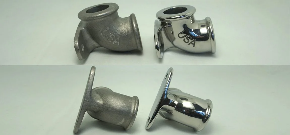
    .jtj-article { max-width: 980px; margin: 0 auto; color: #1f2933; font-family: Arial, Helvetica, sans-serif; font-size: 16px; line-height: 1.72; } .jtj-article * { box-sizing: border-box; } .jtj-article h1, .jtj-article h2, .jtj-article h3 { color: #12212f; line-height: 1.28; margin: 0 0 14px; } .jtj-article h1 { font-size: 34px; margin-bottom: 18px; } .jtj-article h2 { font-size: 24px; margin-top: 36px; } .jtj-article h3 { font-size: 19px; margin-top: 24px; } .jtj-article p { margin: 0 0 16px; } .jtj-article a { color: #0b6fb3; text-decoration: underline; text-underline-offset: 3px; } .jtj-article .jtj-lead { font-size: 18px; color: #344454; margin-bottom: 22px; } .jtj-article .jtj-hero, .jtj-article .jtj-image { margin: 24px 0 28px; } .jtj-article img { width: 100%; height: auto; display: block; border-radius: 6px; } .jtj-article figcaption { color: #607080; font-size: 14px; margin-top: 8px; } .jtj-article .jtj-note, .jtj-article .jtj-cta { border-left: 4px solid #0b6fb3; background: #f2f7fb; padding: 18px 20px; margin: 24px 0; border-radius: 0 6px 6px 0; } .jtj-article .jtj-cta { background: #eef7f2; border-left-color: #25824b; } .jtj-article ul { padding-left: 22px; margin: 0 0 18px; } .jtj-article li { margin-bottom: 8px; } .jtj-article .jtj-table-wrap { overflow-x: auto; margin: 22px 0; border: 1px solid #d8e0e8; border-radius: 6px; } .jtj-article table { width: 100%; min-width: 760px; border-collapse: collapse; background: #fff; } .jtj-article th, .jtj-article td { padding: 12px 14px; border-bottom: 1px solid #e5ebf0; text-align: left; vertical-align: top; } .jtj-article th { background: #f5f8fa; color: #12212f; font-weight: 700; } .jtj-article .jtj-related { display: flex; flex-wrap: wrap; gap: 10px; margin: 18px 0 4px; } .jtj-article .jtj-related a { display: inline-block; border: 1px solid #c9d7e3; border-radius: 999px; padding: 8px 12px; text-decoration: none; background: #fff; color: #164d76; } @media (max-width: 768px) { .jtj-article { font-size: 15px; line-height: 1.68; } .jtj-article h1 { font-size: 27px; } .jtj-article h2 { font-size: 21px; } .jtj-article .jtj-lead { font-size: 16px; } .jtj-article .jtj-note, .jtj-article .jtj-cta { padding: 15px; } } Why Stainless Steel Parts Are Not Bright After Tumbling and How to Improve the Finish A common problem in stainless steel tumbling is this: the burrs are reduced, the surface feels smoother, but the parts still look gray, cloudy, or dull. The operator extends the cycle time, but the finish does not become brighter. In some cases, edges start to round while the surface still does not reach the expected mirror-like appearance. This usually means the process is doing some grinding work, but it is not completing the full surface refinement route. Stainless steel needs the right sequence: remove roughness first, refine the scratch pattern, clean the surface, then use a suitable polishing or burnishing stage. Quick answer: If stainless steel parts are smooth but not bright after tumbling, check the original surface roughness, media cutting grade, polishing stage, compound, water cleanliness, and drying process. A single rough grinding step cannot usually create a bright finish. Most stainless steel parts need controlled smoothing followed by fine polishing or burnishing. First Identify What “Not Bright” Really Means “Not bright” can describe several different surface problems. Before changing the machine or media, inspect the surface under consistent light and decide what defect you are actually seeing. Symptom Likely Cause What to Check Recommended Adjustment Surface is gray and matte Only rough cutting was completed Media grade, cycle sequence, original roughness Add a finer finishing or polishing stage after grinding Surface has visible fine scratches Media is too coarse or previous scratches are not removed Scratch direction, media abrasiveness, processing time Use finer media or extend the intermediate smoothing step Parts are smooth but cloudy Compound residue, dirty water, or poor rinsing Water clarity, compound concentration, media cleanliness Improve rinsing and use a suitable stainless steel finishing compound Edges are rounded but surface is still dull Cycle time is too long in the wrong stage Edge radius, part geometry, process sequence Stop over-processing and separate cutting from polishing Some parts are bright and others are dull Uneven contact, overloading, or part nesting Batch size, part-to-media ratio, part movement Reduce loading density and improve part-media flow Why One Tumbling Step Often Cannot Create a Bright Finish Many production teams expect one tumbling cycle to remove burrs, smooth casting texture, remove machining marks, and create a bright finish. For stainless steel, this is often unrealistic. A media strong enough to remove rough marks can leave its own matte cutting pattern. A media gentle enough to brighten the surface may not remove heavy roughness efficiently. That is why stainless steel finishing is often more stable as a staged process. The first stage reduces roughness and burrs. The second stage refines the surface. A final stage may use polishing media, steel media, or a burnishing process to improve brightness. Check the Starting Surface Before Choosing Media The surface before finishing determines how much work the process must do. Cast stainless steel, welded parts, stamped parts, machined parts, and forged parts all enter tumbling with different surface conditions. If the original surface is very rough, a bright finish cannot be achieved by simply using a mild polishing step. If the original surface only has light tool marks, an overly aggressive grinding step may make the finish worse instead of better. Real stainless steel finishing comparison: brightness depends on the full process sequence, not just longer tumbling time. Choose Media Based on the Stage Ceramic media is useful when the part needs cutting, deburring, edge smoothing, or rough surface reduction. It can prepare stainless steel parts for the next stage, but it may not create a bright final appearance by itself. For a brighter finish, the process may need finer media, polishing media, or steel finishing media depending on the part shape and target surface. If the part has internal cavities, slots, or thin edges, media shape and size must also be checked to avoid lodging or over-rounding. Compound and Water Quality Can Hide a Good Finish Sometimes the mechanical finishing result is acceptable, but the parts still look dull because the surface is covered by residue. Dirty water, abrasive fines, oil, and incorrect compound concentration can leave a gray film on stainless steel. A suitable finishing compound helps clean the surface, suspend removed particles, control foam, and improve brightness. If the process liquid turns dark quickly, or parts become cloudy after drying, check water flow, compound dosage, rinsing, and media cleanliness before changing the machine. Machine Motion and Loading Also Affect Brightness A vibratory finishing machine is commonly used for stainless steel batch finishing because it provides steady media movement. However, brightness can still be inconsistent if the machine is overloaded or if parts shield each other. Long or heavy stainless steel parts may require a tub vibrator to reduce collision damage and improve contact control. Small precision parts may need a different setup if holes, threads, or fine edges are critical. Common Mistakes That Keep Stainless Steel Dull Using one coarse media step and expecting a mirror finish. Extending cycle time until edges round, instead of adding a finer stage. Ignoring the original surface roughness before choosing media. Using dirty process water and then blaming the media. Skipping rinsing and drying control after wet finishing. Overloading the machine so parts do not move freely through the media. Choosing media size without checking holes, slots, and internal cavities. A Practical Test Route for Stainless Steel Brightness For a new stainless steel part, do not start with a full production batch. Test a small quantity and record each stage. A practical test route may include: Stage 1: deburring or surface smoothing with suitable cutting media. Stage 2: finer finishing to reduce the scratch pattern from the first stage. Stage 3: polishing or burnishing to improve brightness. Final check: rinse, dry, and inspect under consistent lighting before judging the result. The final settings should be confirmed with sample parts because stainless steel grade, part geometry, welds, casting texture, and target brightness all affect the process. Related Solutions If you are improving stainless steel surface brightness, these pages may help you compare suitable machines, media, and process consumables: Vibratory Finishing Machine Tub Vibrators Ceramic Media
  • How to Polish Concave Aluminum Parts Without Cloudy Surfaces or Edge Rounding
    How to Polish Concave Aluminum Parts Without Cloudy Surfaces or Edge Rounding May 08 , 2026
    .jtj-article { max-width: 980px; margin: 0 auto; color: #1f2933; font-family: Arial, Helvetica, sans-serif; font-size: 16px; line-height: 1.72; } .jtj-article * { box-sizing: border-box; } .jtj-article h1, .jtj-article h2, .jtj-article h3 { color: #12212f; line-height: 1.28; margin: 0 0 14px; } .jtj-article h1 { font-size: 34px; margin-bottom: 18px; } .jtj-article h2 { font-size: 24px; margin-top: 36px; } .jtj-article h3 { font-size: 19px; margin-top: 24px; } .jtj-article p { margin: 0 0 16px; } .jtj-article a { color: #0b6fb3; text-decoration: underline; text-underline-offset: 3px; } .jtj-article .jtj-lead { font-size: 18px; color: #344454; margin-bottom: 22px; } .jtj-article .jtj-hero, .jtj-article .jtj-image { margin: 24px 0 28px; } .jtj-article img { width: 100%; height: auto; display: block; border-radius: 6px; } .jtj-article figcaption { color: #607080; font-size: 14px; margin-top: 8px; } .jtj-article .jtj-note, .jtj-article .jtj-cta { border-left: 4px solid #0b6fb3; background: #f2f7fb; padding: 18px 20px; margin: 24px 0; border-radius: 0 6px 6px 0; } .jtj-article .jtj-cta { background: #eef7f2; border-left-color: #25824b; } .jtj-article ul { padding-left: 22px; margin: 0 0 18px; } .jtj-article li { margin-bottom: 8px; } .jtj-article .jtj-table-wrap { overflow-x: auto; margin: 22px 0; border: 1px solid #d8e0e8; border-radius: 6px; } .jtj-article table { width: 100%; min-width: 760px; border-collapse: collapse; background: #fff; } .jtj-article th, .jtj-article td { padding: 12px 14px; border-bottom: 1px solid #e5ebf0; text-align: left; vertical-align: top; } .jtj-article th { background: #f5f8fa; color: #12212f; font-weight: 700; } .jtj-article .jtj-related { display: flex; flex-wrap: wrap; gap: 10px; margin: 18px 0 4px; } .jtj-article .jtj-related a { display: inline-block; border: 1px solid #c9d7e3; border-radius: 999px; padding: 8px 12px; text-decoration: none; background: #fff; color: #164d76; } @media (max-width: 768px) { .jtj-article { font-size: 15px; line-height: 1.68; } .jtj-article h1 { font-size: 27px; } .jtj-article h2 { font-size: 21px; } .jtj-article .jtj-lead { font-size: 16px; } .jtj-article .jtj-note, .jtj-article .jtj-cta { padding: 15px; } } How to Polish Concave Aluminum Parts Without Cloudy Surfaces or Edge Rounding Concave aluminum parts are difficult to polish in batch production because the curved recess does not receive the same media contact as flat surfaces. One area may become bright, while the inner curve stays cloudy, matte, or slightly scratched. If the process is made more aggressive, the edges may become rounded before the concave surface is fully corrected. This is a common problem on aluminum housings, decorative fittings, motorcycle parts, lighting components, hardware parts, and curved CNC or die-cast parts. The solution is not simply “run longer.” The process must balance media access, cutting strength, part protection, compound control, and final brightening. Quick answer: If the concave area remains cloudy while outer edges become too rounded, the process is usually too aggressive in the wrong places and too weak inside the recess. Start by checking media size, media shape, part loading, compound, and whether the process needs two stages: controlled smoothing first, then bright polishing. Why Concave Aluminum Surfaces Are Hard to Finish In mass finishing, media removes burrs and improves surfaces through repeated sliding, rolling, and impact contact. Flat outer surfaces receive media contact easily. Concave surfaces are different: media may bridge over the recess, contact only the rim, or move through the curve without enough pressure. This creates a typical production conflict: the outside edge and rim are finished too quickly, but the inner curved surface still looks dull. If the operator extends the cycle time, the edge may lose definition before the recess becomes bright. First Diagnose the Surface Problem Before changing media or machine settings, inspect where the defect appears. A cloudy concave surface can come from different causes, and each cause needs a different correction. Symptom Likely Cause What to Check Recommended Adjustment Concave area is cloudy, rim is bright Media contact is concentrated on the edge Media size, part orientation, recess depth Try smaller or better-shaped media that can enter the curve more evenly Edges are rounded before the inner surface improves Cycle time or cutting strength is too high Edge radius, processing time, media aggressiveness Reduce cutting stage time and separate smoothing from polishing Surface has gray film after finishing Aluminum fines, unsuitable compound, dirty water Water clarity, compound type, media cleanliness Improve rinsing and use aluminum-safe finishing compound Bright finish is uneven from part to part Parts are shielding each other or loading is too dense Part-to-media ratio, batch size, part nesting Reduce loading density and prevent parts from stacking in the bowl Small scratches remain inside the curve Media is too coarse or previous machining marks are deep Initial surface roughness, media grade, polishing sequence Add a finer finishing stage before final bright polishing Choose Media by Geometry, Not Only by Material Aluminum is soft, so plastic media is often safer when visible surfaces must be protected. But for concave parts, media shape and size can be more important than media material alone. If the media is too large, it may only polish the rim and outer surface. If it is too small, it may not create enough pressure or may become difficult to separate. Cone, pyramid, angle-cut, or rounded media should be tested against the actual curve, slot, hole, and edge design of the part. Ceramic media may be useful for the first smoothing stage when machining marks or casting texture are heavy, but it must be controlled carefully on decorative aluminum surfaces. For bright finishing, a gentler stage may be needed after the cutting stage. Real aluminum polishing comparison: the process must improve the curved surface without over-cutting the edge and rim. Do Not Solve Every Problem by Extending Cycle Time Extending cycle time is one of the most common mistakes when concave surfaces do not become bright. It may improve the recess slightly, but it also increases edge rounding, part-on-part contact, media wear, and surface inconsistency. A better approach is to adjust contact quality. That may mean changing media shape, lowering batch load, improving liquid flow, or using a two-step process. For many aluminum parts, the first stage should remove marks and smooth the surface; the second stage should refine brightness without excessive cutting. Control Part Loading and Nesting Concave parts can nest together during finishing. When parts stack or shield each other, some surfaces receive little media contact while exposed edges receive too much. This is especially common with cup-shaped, cap-shaped, and curved aluminum parts. If nesting happens, reduce the batch size, increase media support, or test a different machine motion. A standard vibratory finishing machine works well for many aluminum parts, but long, fragile, or easily nested parts may need controlled loading or a different finishing setup. Use Compound to Keep Aluminum Clean Aluminum fines can make the surface look gray or cloudy after finishing. The right finishing compound helps suspend removed particles, reduce smut, improve lubrication, and keep the surface cleaner during wet processing. If the water turns dark quickly or parts look gray after rinsing, check compound concentration, water flow, media cleanliness, and whether the process liquid is being replaced often enough. A cloudy surface is not always a polishing problem; sometimes it is a cleaning and chemistry problem. When to Use a Two-Stage Process A single process may not be enough when the part has machining marks, a concave curve, and a bright appearance requirement. In that case, separating the work into two stages is more stable. Stage 1: controlled smoothing to reduce machining marks, burrs, and roughness without excessive edge loss. Stage 2: finer finishing or polishing to improve brightness and surface uniformity. Final check: inspect the concave area, rim, slots, holes, and any visible edge under consistent lighting. If water marks appear after the wet stage, add or improve the drying step. For bright aluminum parts, quick rinsing and controlled drying can be as important as media selection. Industrial dryers may help keep the final surface consistent. Common Mistakes to Avoid Using a strong cutting media because the concave area is still cloudy. Increasing cycle time until the rim becomes rounded. Choosing media only by aluminum material, without checking recess depth and curve radius. Loading too many parts so concave surfaces shield each other. Ignoring dirty water, aluminum fines, and compound residue when diagnosing cloudy surfaces. Expecting one process to remove rough marks and create a bright finish at the same time. Related Solutions If you are building a stable process for concave aluminum parts, these pages may help you compare suitable machines, media, compounds, and drying equipment: Vibratory Finishing Machine Plastic Media Ceramic Media Finishing Compounds Industrial Dryers Finishing Applications Need a Polishing Test for Concave Aluminum Parts? Send us your aluminum part photos, alloy, concave depth, edge requirements, current surface condition, and target finish. JINTAIJIN can help review whether the process should use plastic media, ceramic media, a two-stage polishing route, or a different loading method. Contact our finishing team for concave aluminum polishing support
  • Ceramic Media vs Plastic Media: How to Choose the Right Tumbling Media Apr 29 , 2026
    Ceramic Media vs Plastic Media: How to Choose the Right Tumbling Media Choosing between ceramic media and plastic media is one of the most important decisions in a mass finishing process. The right media can remove burrs, smooth edges, improve surface consistency, and reduce manual work. The wrong media can damage parts, leave poor finishes, lodge in holes, or make cycle time unnecessarily long. This guide explains how ceramic and plastic tumbling media behave differently, where each type works best, and how to choose the right option for your material, burr condition, part geometry, and target finish. Quick answer: Ceramic media is usually better for stronger cutting, deburring, and edge breaking. Plastic media is usually better for softer metals, delicate parts, pre-polishing, and reducing part-on-part damage. The final choice should also consider media shape, media size, part holes, surface target, and sample testing results. What Is Ceramic Media? Ceramic media is a dense tumbling media made with abrasive materials bonded into different shapes, such as triangles, cylinders, angle cuts, cones, and balls. Because it is harder and heavier than plastic media, it usually provides stronger cutting action. Ceramic media is often used when parts need burr removal, edge radiusing, oxide removal, scale removal, or general surface smoothing before further polishing, coating, plating, or assembly. Common ceramic media advantages Good cutting strength for medium to heavy burrs. Long service life compared with many softer media types. Suitable for steel, stainless steel, iron, copper, brass, and many cast parts. Available in many shapes and sizes for different part geometries. Works well in many vibratory finishing machine applications. What Is Plastic Media? Plastic media is lighter than ceramic media and is commonly used for softer metals or parts that need a gentler finishing action. It is often selected for aluminum, zinc alloy, brass, magnesium alloy, and die-cast components where aggressive media may cause dents, peening, or excessive edge rounding. Plastic media is also useful when the goal is to create a smoother pre-polish surface instead of only removing heavy burrs. Common plastic media advantages Gentler action on soft metals and decorative parts. Lower risk of part-on-part damage compared with heavier media. Good for aluminum die castings, zinc alloy parts, and precision machined parts. Useful for pre-polishing and surface smoothing before final finishing. Available in cone, pyramid, wedge, and other shapes for complex surfaces. Ceramic media normally provides stronger cutting, while plastic media is often used for softer materials and more controlled surface finishing. Ceramic Media vs Plastic Media Comparison Factor Ceramic Media Plastic Media Cutting strength Medium to strong cutting action Light to medium cutting action Media weight Heavier, more impact force Lighter, gentler on parts Best for Steel, stainless steel, iron, harder alloys, cast parts Aluminum, zinc alloy, brass, magnesium alloy, softer metals Typical purpose Deburring, edge breaking, scale removal, surface smoothing Pre-polishing, light deburring, surface refinement, damage reduction Risk May be too aggressive for delicate or soft parts May be too slow for heavy burrs or hard materials Surface result More cutting marks if aggressive grades are used Smoother, more controlled surface before polishing How to Choose the Right Media A good media choice starts with the part, not with the media catalog. Before selecting a media type, check the material, part size, burr size, surface target, hole dimensions, slot width, and whether the part can tolerate impact. Choose ceramic media when... The burr is medium or heavy. The material is harder or more wear-resistant. You need edge breaking before coating or assembly. Cycle time must be efficient for batch production. Choose plastic media when... The part is aluminum, zinc alloy, or another softer metal. The surface must avoid dents or heavy impact marks. You need light deburring or pre-polishing. The part has decorative or visible surfaces. Do Not Ignore Media Shape and Size Media material is only one part of the decision. Shape and size can be just as important. A good media should reach the surface that needs finishing, but it should not lodge inside holes, threads, slots, or blind cavities. For parts with complex geometry, test different shapes before mass production. Triangle media may work well for corners and flat surfaces, while cone or pyramid media may reach different edges. Rounder shapes may reduce lodging risk in some parts, but may not cut as efficiently in narrow areas. Machine and Compound Also Affect the Result The same media can behave differently in different machines. A standard vibratory bowl, tub vibrator, barrel finishing machine, or centrifugal finishing system can all create different contact patterns between parts and media. Finishing compounds also matter. They help clean the surface, control foam, improve lubrication, suspend removed particles, and stabilize the finishing process. If compound concentration or water flow is wrong, even the correct media may produce unstable results. Common Selection Mistakes Choosing ceramic media only because it cuts faster, even when the part is soft or easily damaged. Choosing plastic media for heavy burrs that actually require stronger cutting action. Ignoring holes, slots, threads, and internal cavities before choosing media size. Using one media type for every material and every part shape. Judging the process only by surface appearance without checking cycle time, lodging, separation, and manual rework. Recommended Testing Method For a new part, sample testing should compare at least two or three media options. The test should measure burr removal, edge condition, surface uniformity, part damage, media lodging, separation efficiency, and total cycle time. A typical starting range may include different media materials, shapes, and sizes. Final settings should be tested with sample parts because small changes in part geometry can completely change the result. Related Solutions If you are comparing media for a real production project, these pages can help you review equipment and consumables: Ceramic Media Plastic Media Grinding Media Vibratory Finishing Machine Finishing Applications Need Help Choosing Tumbling Media? Send us your part material, size, burr condition, current surface, target finish, and production quantity. JINTAIJIN can help recommend suitable ceramic media, plastic media, compounds, and a sample testing process for your parts. Contact our finishing team for media selection support .jtj-article { max-width: 980px; margin: 0 auto; color: #1f2933; font-family: Arial, Helvetica, sans-serif; font-size: 16px; line-height: 1.72; } .jtj-article * { box-sizing: border-box; } .jtj-article h1, .jtj-article h2, .jtj-article h3 { color: #12212f; line-height: 1.28; margin: 0 0 14px; } .jtj-article h1 { font-size: 34px; margin-bottom: 18px; } .jtj-article h2 { font-size: 24px; margin-top: 36px; } .jtj-article h3 { font-size: 19px; margin-top: 24px; } .jtj-article p { margin: 0 0 16px; } .jtj-article a { color: #0b6fb3; text-decoration: underline; text-underline-offset: 3px; } .jtj-article .jtj-lead { font-size: 18px; color: #344454; margin-bottom: 22px; } .jtj-article .jtj-hero, .jtj-article .jtj-image { margin: 24px 0 28px; } .jtj-article img { width: 100%; height: auto; display: block; border-radius: 6px; } .jtj-article figcaption { color: #607080; font-size: 14px; margin-top: 8px; } .jtj-article .jtj-note, .jtj-article .jtj-cta { border-left: 4px solid #0b6fb3; background: #f2f7fb; padding: 18px 20px; margin: 24px 0; border-radius: 0 6px 6px 0; } .jtj-article .jtj-cta { background: #eef7f2; border-left-color: #25824b; } .jtj-article ul { padding-left: 22px; margin: 0 0 18px; } .jtj-article li { margin-bottom: 8px; } .jtj-article .jtj-grid { display: grid; grid-template-columns: repeat(2, minmax(0, 1fr)); gap: 16px; margin: 22px 0; } .jtj-article .jtj-card { border: 1px solid #d8e0e8; border-radius: 6px; padding: 18px; background: #fff; } .jtj-article .jtj-table-wrap { overflow-x: auto; margin: 22px 0; border: 1px solid #d8e0e8; border-radius: 6px; } .jtj-article table { width: 100%; min-width: 760px; border-collapse: collapse; background: #fff; } .jtj-article th, .jtj-article td { padding: 12px 14px; border-bottom: 1px solid #e5ebf0; text-align: left; vertical-align: top; } .jtj-article th { background: #f5f8fa; color: #12212f; font-weight: 700; } .jtj-article .jtj-related { display: flex; flex-wrap: wrap; gap: 10px; margin: 18px 0 4px; } .jtj-article .jtj-related a { display: inline-block; border: 1px solid #c9d7e3; border-radius: 999px; padding: 8px 12px; text-decoration: none; background: #fff; color: #164d76; } @media (max-width: 768px) { .jtj-article { font-size: 15px; line-height: 1.68; } .jtj-article h1 { font-size: 27px; } .jtj-article h2 { font-size: 21px; } .jtj-article .jtj-lead { font-size: 16px; } .jtj-article .jtj-grid { grid-template-columns: 1fr; } .jtj-article .jtj-note, .jtj-article .jtj-cta, .jtj-article .jtj-card { padding: 15px; } }
  • How to Prevent Tumbling Media from Lodging in Holes, Slots, and Threads
    How to Prevent Tumbling Media from Lodging in Holes, Slots, and Threads Apr 29 , 2026
    How to Prevent Tumbling Media from Lodging in Holes, Slots, and Threads Media lodging is one of the most common problems in mass finishing. When ceramic, plastic, or steel media gets stuck inside holes, slots, grooves, threads, or blind cavities, it slows production, increases manual cleaning work, and may even damage finished parts. The good news is that most lodging problems can be reduced before production starts. The key is to match the part geometry with the right machine motion, media shape, media size, compound, separation method, and process time. This guide explains how to diagnose the cause and build a more reliable finishing process. Quick answer: If media is lodging in your parts, first check whether the media size is close to the hole, slot, or thread dimension. Then review media shape, machine type, water flow, compound lubrication, and unloading method. For complex parts, sample testing is usually the safest way to confirm the process before mass production. Why Media Gets Stuck in Parts Media lodging usually happens when the media can enter a feature but cannot escape easily during the finishing cycle. This is common on CNC parts, die castings, machined aluminum parts, stainless steel components, zinc alloy parts, and small precision hardware. Geometry mismatch If the media size is too close to the hole, slot, groove, or thread pitch, it can wedge into the part during vibration or tumbling. Wrong media shape Triangles, cones, cylinders, balls, and angle-cut media behave differently. A shape that works well on open surfaces may lodge inside blind holes. Excessive cutting action Stronger cutting media can push into edges and recesses more aggressively, especially when the part has sharp transitions or deep pockets. Poor separation Even if media does not lodge during processing, it may remain inside cavities if the unloading, rinsing, or screening step is not designed well. Start with Part Geometry, Not the Machine Before choosing a vibratory finishing machine or any other mass finishing equipment, inspect the part features that may trap media. The most important dimensions are hole diameter, slot width, groove depth, thread size, blind cavity depth, and the direction of openings. A simple rule is to avoid media that can enter a feature and rotate into a locked position. For example, a media piece that is slightly smaller than a hole may enter easily but become difficult to remove after vibration, especially if the hole is deep or threaded. Media Selection Guide for Lodging Prevention Part Feature Common Risk Better Media Choice Process Note Small through holes Media enters and blocks the hole Use media larger than the hole, or much smaller if it can pass through freely Avoid media size close to the hole diameter Blind holes Media enters but cannot exit Consider rounded or non-wedging shapes Rinsing and air blow-off may be required after finishing Narrow slots Angle-cut media wedges into the slot Use rounder shapes or adjust media size Check slot width and depth before production Threads Media locks into thread pitch Use smaller smooth media or avoid aggressive angular shapes Protect critical threads when tight tolerance is required Complex die castings Media remains in ribs, pockets, or cavities Test plastic media or selected ceramic shapes Design separation into the process, not as an afterthought Ceramic Media or Plastic Media? Ceramic media is often used for stronger deburring, edge breaking, and surface smoothing. It is durable and effective, but some shapes may lodge in holes or slots if the size is not selected carefully. Plastic media is usually lighter and more suitable for softer metals, aluminum parts, zinc alloy die castings, and parts where surface impact must be reduced. For parts with delicate edges or decorative surfaces, plastic media can reduce part-on-part damage and help create a more controlled finish. The best choice depends on the material, burr size, target surface, and part geometry. For parts with many holes and recesses, media shape and size are often more important than simply choosing ceramic or plastic. Machine Motion Also Matters Different machines move parts and media in different ways. A standard vibratory bowl is efficient for many batches, while tub vibrators are often used for longer or larger components. Barrel finishing machines can be useful for gentler rolling action, while centrifugal systems may shorten cycle time for suitable parts. If lodging happens repeatedly, do not only change media. Review the complete process: machine loading ratio, water level, compound concentration, part-to-media ratio, cycle time, and separation method. Use Compound and Water Flow Correctly Finishing compounds help clean the surface, control foam, suspend removed particles, and improve media movement. Poor lubrication can increase friction and make media more likely to wedge into part features. In wet finishing, water and compound should support smooth rolling action. Too little liquid may make the mass too dry and aggressive. Too much liquid may reduce finishing efficiency and affect media movement. The correct range depends on the machine, media, and part load, so sample testing is recommended before production. Common Mistakes to Avoid Choosing media only by cutting strength without checking hole and slot dimensions. Using one media shape for every part in the factory. Running longer cycle times to solve a problem that is actually caused by wrong media size. Ignoring unloading and separation until after the process is already fixed. Using aggressive media on delicate threaded or precision-machined parts without testing. Forgetting to check whether media can be removed by rinsing, screening, air blow-off, or manual inspection. Recommended Testing Process For parts with holes, slots, threads, or internal cavities, the safest approach is to test several media options before confirming mass production. A practical test should compare finishing result, burr removal, surface roughness, lodging rate, separation efficiency, and total cycle time. Testing tip: Do not judge the process only by how the outer surface looks. After testing, inspect every hole, slot, thread, and blind cavity. A process that gives a good surface but requires heavy manual media removal is usually not stable enough for batch production. Related Solutions If you are building or improving a mass finishing process, these pages may help you compare suitable equipment and consumables: Vibratory Finishing Machine Ceramic Media Plastic Media Finishing Compounds Finishing Applications Need Help Choosing Media for Complex Parts? If your parts have holes, slots, grooves, threads, or blind cavities, send us the part material, dimensions, current surface condition, burr condition, and target finish. Our finishing team can help recommend a suitable machine, media shape, compound, and sample testing process. Contact JINTAIJIN to discuss your finishing process .jtj-article { color: #1f2933; font-family: Arial, Helvetica, sans-serif; line-height: 1.72; font-size: 16px; max-width: 980px; margin: 0 auto; } .jtj-article * { box-sizing: border-box; } .jtj-article h1, .jtj-article h2, .jtj-article h3 { color: #12212f; line-height: 1.28; margin: 0 0 14px; } .jtj-article h1 { font-size: 34px; margin-bottom: 18px; } .jtj-article h2 { font-size: 24px; margin-top: 36px; } .jtj-article h3 { font-size: 19px; margin-top: 24px; } .jtj-article p { margin: 0 0 16px; } .jtj-article a { color: #0b6fb3; text-decoration: underline; text-underline-offset: 3px; } .jtj-article .jtj-lead { font-size: 18px; color: #344454; margin-bottom: 22px; } .jtj-article .jtj-hero { margin: 24px 0 28px; } .jtj-article .jtj-hero img { width: 100%; height: auto; border-radius: 6px; display: block; } .jtj-article .jtj-note, .jtj-article .jtj-cta { border-left: 4px solid #0b6fb3; background: #f2f7fb; padding: 18px 20px; margin: 24px 0; border-radius: 0 6px 6px 0; } .jtj-article .jtj-cta { background: #eef7f2; border-left-color: #25824b; } .jtj-article ul { padding-left: 22px; margin: 0 0 18px; } .jtj-article li { margin-bottom: 8px; } .jtj-article .jtj-grid { display: grid; grid-template-columns: repeat(2, minmax(0, 1fr)); gap: 16px; margin: 22px 0; } .jtj-article .jtj-card { border: 1px solid #d8e0e8; border-radius: 6px; padding: 18px; background: #fff; } .jtj-article .jtj-table-wrap { overflow-x: auto; margin: 22px 0; border: 1px solid #d8e0e8; border-radius: 6px; } .jtj-article table { width: 100%; border-collapse: collapse; min-width: 720px; background: #fff; } .jtj-article th, .jtj-article td { padding: 12px 14px; border-bottom: 1px solid #e5ebf0; text-align: left; vertical-align: top; } .jtj-article th { background: #f5f8fa; color: #12212f; font-weight: 700; } .jtj-article .jtj-related { display: flex; flex-wrap: wrap; gap: 10px; margin: 18px 0 4px; } .jtj-article .jtj-related a { display: inline-block; border: 1px solid #c9d7e3; border-radius: 999px; padding: 8px 12px; text-decoration: none; background: #fff; color: #164d76; } @media (max-width: 768px) { .jtj-article { font-size: 15px; line-height: 1.68; } .jtj-article h1 { font-size: 27px; } .jtj-article h2 { font-size: 21px; } .jtj-article .jtj-lead { font-size: 16px; } .jtj-article .jtj-grid { grid-template-columns: 1fr; } .jtj-article .jtj-note, .jtj-article .jtj-cta, .jtj-article .jtj-card { padding: 15px; } }
  • Copper Alloy Bathroom Fixture Polishing: Tumbling Finishing Machine Achieves Mirror Finish
    Copper Alloy Bathroom Fixture Polishing: Tumbling Finishing Machine Achieves Mirror Finish Sep 04 , 2025
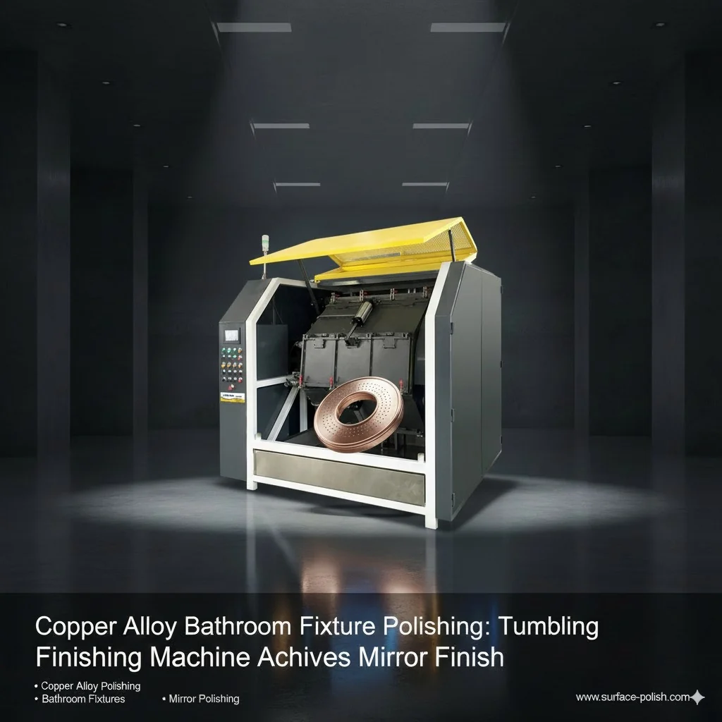
    Copper Alloy Bathroom Fixture Polishing: Tumbling Finishing Machine Achieves Mirror Finish In the world of high-end design, the appeal of copper alloy bathroom fixtures is undeniable. Their warmth and elegance can elevate any space, but achieving a flawless, durable mirror polishing finish is a significant manufacturing challenge. This article explores how our advanced machinery provides the perfect solution: Copper Alloy Bathroom Fixture Polishing: Tumbling Finishing Machine Achieves Mirror Finish. The Challenge: Flawless Surfaces on Complex Shapes Bathroom fixtures like faucets, handles, and showerheads have intricate designs with curves and hard-to-reach areas. Traditional hand polishing is labor-intensive, costly, and often results in inconsistent finishes. The goal is to achieve a uniform, high-gloss luster across the entire surface—a task perfectly suited for automated mass finishing solutions. The Solution: High-Efficiency Vibratory Finishing The key to pristine copper alloy polishing lies in automated, precision-controlled processes. Our Tumbling Finishing Machine offers a superior method for deburring, smoothing, and polishing large batches of parts simultaneously. This vibratory finishing process ensures that every angle and contour of a fixture receives uniform treatment, resulting in a consistent, high-quality mirror finish that manual methods cannot replicate. The Three-Stage Process to Perfection Achieving a mirror finish is a multi-step process that relies on the careful selection of equipment and materials. Stage 1: Deburring & Surface Preparation: The initial step uses a coarser-grade media to remove any burrs, parting lines, or surface imperfections from the raw copper alloy parts, creating a smooth, uniform foundation. Stage 2: Smoothing with Abrasives: Next, a finer abrasive medium is introduced. This stage smooths the surface further, removing the microscopic scratches left from the first stage and preparing it for the final polish. The choice of abrasive materials is critical for achieving optimal results. Stage 3: Mirror Polishing: The final stage uses a specialized polishing compound along with soft, non-abrasive media. This combination buffs the copper alloy surface to a brilliant, reflective mirror shine. We have documented remarkable transformations using this method. For a detailed look at the results, view our bathroom fixture polishing case studies. Adhering to Industry Standards Producing a quality finish goes beyond aesthetics; it involves durability and performance. Meeting industry benchmarks is crucial for ensuring longevity and corrosion resistance. For more information on the technical requirements, we recommend reviewing the Technical Specifications for Bathroom Metal Polishing to understand the standards that govern superior metal finishes. Ready to Achieve a Perfect Mirror Finish? Elevate the quality and efficiency of your production line. Explore our state-of-the-art tumbling finishing machines today. Discover Our Machines document.addEventListener("DOMContentLoaded", function() { const images = document.querySelectorAll('.article-image'); const observerOptions = { root: null, rootMargin: '0px', threshold: 0.1 }; const observer = new IntersectionObserver((entries, observer) => { entries.forEach(entry => { if (entry.isIntersecting) { entry.target.classList.add('fade-in'); observer.unobserve(entry.target); } }); }, observerOptions); images.forEach(image => { observer.observe(image); }); }); ``` /* ----- Basic Styling & Fonts ----- */ @import url("data:,"); .polish-article-container { font-family: 'Roboto', sans-serif; color: #333; line-height: 1.8; background-color: #fff; max-width: 900px; margin: 40px auto; padding: 40px; border-radius: 8px; box-shadow: 0 6px 20px rgba(0, 0, 0, 0.08); } /* ----- Typography & Headings ----- */ .polish-article-container h1, .polish-article-container h2, .polish-article-container h3 { font-family: 'Montserrat', sans-serif; font-weight: 700; color: #1A3A5D; /* Deep Blue */ margin-bottom: 20px; text-align: center; } .polish-article-container h1 { font-size: 2.6em; margin-bottom: 25px; } .polish-article-container h2 { font-size: 2em; border-bottom: 3px solid #D4A056; /* Gold accent */ padding-bottom: 10px; margin-top: 50px; } .polish-article-container h3 { font-size: 1.5em; color: #2c3e50; text-align: left; } /* ----- Links & Content Styling ----- */ .polish-article-container p { margin-bottom: 25px; font-size: 1.1em; } .polish-article-container a { color: #D4A056; /* Gold */ text-decoration: none; font-weight: 600; transition: color 0.3s ease, border-bottom 0.3s ease; border-bottom: 1px dotted #D4A056; } .polish-article-container a:hover { color: #1A3A5D; /* Deep Blue */ border-bottom: 1px solid #1A3A5D; } /* ----- Image Styling ----- */ .article-image { width: 100%; height: auto; border-radius: 8px; margin: 20px 0 30px 0; box-shadow: 0 4px 12px rgba(0,0,0,0.1); opacity: 0; transform: scale(0.95); transition: opacity 0.8s ease-out, transform 0.8s ease-out; } .article-image.fade-in { opacity: 1; transform: scale(1); } /* ----- Call to Action (CTA) Styling ----- */ .cta-section { background-color: #f4f7f9; border: 2px solid #e1e8ed; border-radius: 8px; padding: 35px; text-align: center; margin-top: 50px; } .cta-section h3 { text-align: center; margin-bottom: 20px; } .cta-button { display: inline-block; background-color: #D4A056; /* Gold */ color: #fff; padding: 15px 35px; border-radius: 5px; font-size: 1.1em; font-weight: 700; text-transform: uppercase; letter-spacing: 1px; border-bottom: none; transition: background-color 0.3s ease, transform 0.3s ease; } .cta-button:hover { background-color: #BF904C; color: #fff; transform: translateY(-3px); } /* ----- List Styling ----- */ .styled-list { list-style-type: none; padding-left: 0; } .styled-list li { position: relative; padding-left: 30px; margin-bottom: 15px; font-size: 1.1em; } .styled-list li:before { content: '✓'; position: absolute; left: 0; top: 0; color: #D4A056; /* Gold */ font-weight: bold; font-size: 1.2em; }
  • Titanium Aerospace Polishing: Centrifugal Disc Finishing for High-Strength Metals-surface-polish.com
    Titanium Aerospace Polishing: Centrifugal Disc Finishing for High-Strength Metals-surface-polish.com Aug 22 , 2025
    Why centrifugal disc finishing for titanium aerospace parts? Centrifugal disc systems deliver very high relative velocities between media and parts,enabling efficient deburring,e

#+86-592-2381506

Email : info@surface-polish.com

Headquarters address : No. 31, Xinchang Road, Xinyang Industrial Zone, Haicang District, Xiamen

click here to leave a message

Leave A Message
If you are interested in our products and want to know more details,please leave a message here,we will reply you as soon as we can.

Preparing secure enquiry form…

Home

Products

whatsapp

contact