A production planner in Nagoya, Japan needs several thousand small stainless bushings finished for aerospace components with consistent edges and no roll beyond a defined chamfer band. SurfacePolish supplies barrel, centrifugal and vibratory machines and the media to run them, and a free sample trial can compare media size classes on the buyer's own parts before any equipment decision is made. This brief is written for a buyer in Nagoya working on aerospace components; it describes equipment, media and a scoped sample review, not a local polishing service.
What edge condition is actually specified at each critical location, and which machine and media combination can hold inside that band?
Which datum and mating surfaces carry assembly geometry, and is a flatness or fit check required on them after finishing?
Does the compound chemistry family create a hydrogen, staining or residue risk for this alloy and heat treatment, and who verifies that?
Material leaves an edge far faster than it leaves an adjacent face on every mechanical finishing route, and on aerospace parts edge condition is frequently a specified requirement rather than a byproduct. Drawings may call out a defined radius, a broken edge or an edge that must remain sharp for a sealing or shearing function. Record the pre-finish edge state with an optical comparator, radius gauges or a cast impression before processing, then set the allowable band in writing. Fatigue-critical holes are the classic case: an edge that is too sharp concentrates stress, while one that is over-rounded changes the bearing area of a fastener head. Because stock removal at an edge is far faster than on a flat face, cycle intensity and media size class are the levers that control it. If edge limits are tight, plan an edge-specific operation rather than hoping a bulk cycle will land inside the band.
Disc finishing machines generate fast cycles by driving media and parts between a rotating disc and the chamber wall, which raises energy at the part surface and shortens the time needed to blend an edge or refine a face. That energy is the trade: flat plates, simple brackets and robust turned parts finish quickly and evenly, while assemblies with thin sections, brazed joints, unsupported flanges or already-tight edge limits can suffer edge rolling, local distortion or part-on-part marking. Geometry limits are real, since a part that is larger than the working gap or too light to stay in the media stream will not be processed predictably. The route deserves evaluation when removal rate and cycle time dominate and the part is simple and robust. Where a part is complex or expensive, disc finishing is more often a stage for one defined face than a whole-part answer.
| Machine route | Where it fits | What it will not do |
|---|---|---|
| Centrifugal barrel finishing machine | Short cycles on small, hard, robust parts where high pressure at the part-media interface is acceptable. | High energy transfers into thin walls and fixtures and wears liners; part size and barrel geometry bound what can be run. |
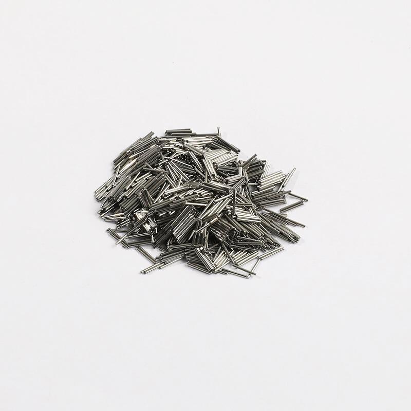
| Magnetic finishing machine | Small precise parts with internal edges and recesses that loose media cannot enter, using small pins or needles. | Bounded by part size and mass, by workpiece material attraction to the pins, and by the need to retrieve residual pins. |
| Vibratory finishing machine, bowl type | General edge blending and surface refinement on medium-sized parts with a continuous, visible load. | Part size is capped by chamber geometry, and thin or delicate parts may need compartments or fixtures to limit part-on-part contact. |
| Vibratory tub or long-channel machine | Long shafts, tubes, housings and large parts that will not turn or circulate in a bowl. | Media circulation is less uniform along a long chamber, and bridging can leave sections of a long bore unprocessed. |
Plastic media removes material gently through a light cutting and burnishing action and is the usual first candidate for aluminum, thin-wall sections and parts where a soft surface must not be scored. Its lower density and hardness mean it conforms rather than cuts deeply, which protects delicate features but also makes it slower and less effective in deep recesses and tight radii where a harder medium is needed to reach. Wear behaviour is different from ceramic: plastic media deform, lose sharpness and load with metal fines, so a blend can look intact while its cut rate has collapsed. Dry media in the same family, such as walnut shell and corn cob, is used for light deburring and drying support rather than for aggressive stock removal. Choose plastic when feature preservation dominates and the required removal is light; verify by measuring the same locations before and after rather than judging by appearance.
| Media | Best fit | Watch out for |
|---|---|---|
| Ceramic media, angle-cut and triangular shapes | Heavier deburring and edge blending on steel, stainless and titanium parts with accessible corners and recesses. | Wears down and changes effective size class, generates sludge, and can chip or over-round thin sections and soft alloys. |
| Plastic media, cones and triangles | Gentle cutting on aluminium, thin-wall sections and surfaces that must not be scored. | Deforms and loads with metal fines so cut rate falls while the blend still looks intact; ineffective in deep recesses and tight radii. |
| Compound with corrosion inhibitor for sensitive alloys | Aluminium and stainless parts that must not stain or pit during processing and between-stage handling. | Inhibitor does not compensate for hard or chloride-bearing water, and residue left in recesses can mask later inspection. |
| Steel media for burnishing | Bright, uniform appearance with minimal dimensional change on parts whose geometry must stay as machined. | Presses debris and hard-water deposits into the surface, concentrates energy on thin sections, and carries iron cross-contamination risk. |
Impingement shows up as a local patch of heavier material removal, a gouge or a flattened edge where media or another part struck the surface with too much energy. On aerospace work it appears most often on thin webs, long unsupported sections, sharp external corners and parts run at too high an amplitude in a lightly loaded chamber. The cause is rarely the medium alone; it is the combination of energy setting, media size and mass, load volume and the freedom of parts to move against each other. Check for it by inspecting known vulnerable features under magnification before and after, by photographing under raking light rather than diffuse light, and by comparing the same feature across several parts from the load. Mitigation follows the diagnosis: reduce amplitude, add media, compartmentalise or fixture the part, or move the operation to a gentler route.
| Failure mode | Likely cause | How to catch it |
|---|---|---|
| Uneven finish across a batch or across one part | Load volume outside the chamber's working range, parts blocking one another, mixed part sizes, or inconsistent fixturing and media distribution. | Measure surface texture at several recorded locations on multiple parts from the same load and record the load pattern alongside the results. |
| Dark or heat-tinted patch following the media flow | Lean compound concentration or restricted flow, letting metal fines and heat build up in the working mass. | Compare against the agreed appearance master under fixed lighting and check the measured compound concentration and flow rate recorded for the batch. |
| Dimensional drift on a close-tolerance bore or spigot | Total removal accumulating over a long cycle or repeated passes without a start-of-run measurement on a critical feature. | Measure critical dimensions on the first part and at defined intervals through the batch, keeping the process effect separate from incoming variation. |
| Edge radius grown past the drawing limit | Cycle time, energy setting or media size class allowing continued edge removal after the adjacent face has stabilised. | Compare the recorded pre-finish edge state with the finished state using radius gauges, an optical comparator or a cast impression at fixed positions. |
Nagoya anchors one of Japan's three major economic zones, an area the city describes as built on 'manufacturing industries' such as ceramics, automobiles and machine tools. Nagoya City's own industry report states that Aichi Prefecture's value of manufactured goods shipments was 47,894.6 billion yen in 2021, 14.5 per cent of the national total, holding first place among prefectures for 45 consecutive years since 1977. The city publishes the annual 'Industry of Nagoya' report covering manufacturing, wholesale and retail trade, services and trade through Nagoya Port and Chubu Centrair International Airport, and its industrial vision to 2028 sets out startup, SME resilience and human-capital programmes. The region is served by Nagoya Port, which the port authority says has become first in Japan for total cargo handled.
For this brief the relevant part of that base is aerospace: Aichi Prefecture operates the 'Asia No.1 Aerospace Industry Cluster Special Zone' and maintains a promotion council for it, and Nagoya City's industry report records municipal support for maintaining aerospace industry certification.
The Nagoya area's automotive and machine-tool base runs on high-volume, high-tolerance parts, where burrs and edge condition affect assembly fit, fatigue behaviour and the cleanliness of subsequent heat treatment, coating or washing steps. Aerospace work adds a certification dimension: Nagoya City has funded support specifically for maintaining aerospace industry certification, so surface and process records must survive audit as well as meet the drawing.
A Nagoya buyer should establish whether the finishing operation is inside or outside its quality-system scope, because automotive and aerospace customers here audit process records and certification, not only the delivered surface.
Freight context: Port of Nagoya (名古屋港) — first in Japan for total cargo handled, with terminals under the Nagoya Port Authority, Chubu Centrair International Airport (中部国際空港), opened 2005. The Nagoya Port Authority states that the port, open since 10 November 1907, has developed as the logistics backbone of manufacturing industry in the Chubu region and is now first in Japan for total cargo handled. Nagoya City's industry report records Nagoya Port's 2023 trade value at 22,512.3 billion yen, up 5.2 per cent year on year, and the port authority publishes monthly and annual statistics series for freight planning.
Chinese industrial machinery entering Japan is classified under the Customs Tariff Law, whose harmonised schedule sets the classification and the General Rate; the Temporary Tariff Measures Law sets a Temporary Rate for certain products, and where the WTO rate or an EPA rate for the goods is lower, that lower rate is applied. The applied rate therefore depends on the exact commodity code, and on whether an economic partnership agreement covers the goods and their origin, so a landed-cost figure has to be confirmed against the specific machine before it is quoted. Japan Customs' monthly country table for August 2026 records exports to China of 1,809,133 million yen and imports from China of 2,361,239 million yen, the largest single-country line in the Asian table, with imports from China up 22.5 per cent year on year.
The national standards body is the Japanese Industrial Standards Committee (JISC), which states that JIS covers industrial and mineral products, data, services and management systems under the Industrial Standardization Act. Its technical divisions include mechanical engineering, ferrous materials and metallurgy, nonferrous materials and metallurgy, ceramics, medical equipment and safety appliances, and aircraft and aviation, which are the divisions a finishing or deburring requirement is normally read against. Product certification runs through the JIS Mark Certification Scheme, operated by accredited certification bodies compliant with ISO/IEC 17065; as of March 2019 there were 24 JIS-accredited bodies, three of them outside Japan, with about 8,700 certifications issued, and the scheme explicitly covers foreign manufacturers, processors and exporters.
SurfacePolish supplies from Xiamen, China. The buyer's own destination rules, conformity marking, tariff classification and documentation responsibilities stay with the buyer; confirm them against the authorities named above before ordering.
Acceptance begins with a written decision about how many parts are examined and which one is the reference. A workable plan names the sample size per batch, the inspection frequency, the measurement locations and the person responsible for accepting or rejecting. A first article should be fully inspected against the drawing and the agreed requirements, then retained as the physical reference for later comparison, because appearance memory is unreliable across shifts. For lower-volume aerospace work, the sensible pattern is to inspect the first part of each batch completely, examine a defined sample through the run and inspect critical features on every part when the feature is safety-relevant or the process is not yet stable. Fix these rules before the first production batch, when there is still room to argue about the requirement rather than about the parts.
Comparative trials lose their value when several things change together. Fix the machine, load volume, part count, compound concentration and cycle time, then change one variable: media material first, then size class, then compound, then time or energy setting. Ask for the same recorded locations to be measured with the same instrument and the same setting across all variants, and for photographs taken under identical lighting, so the comparison is between processes rather than between photographers. Retain all tested parts, including the ones that went wrong, because a rejected variant often explains which mechanism caused a defect and therefore which limit must be respected in production. A comparison of two media blends run with different cycle times and different operators tells you nothing about the media, which is the most common reason a trial result fails to transfer into a line.


Ask for records that let a later batch be compared with the approved one: machine and bath identification, media type and size class, compound product and measured concentration, cycle time and energy setting, load weight or part count, rinse and dry method, and measurement results with the instrument, setup and locations. Photographs taken under consistent lighting before and after belong in the record, along with any deviation raised during the run. A document that only asserts quality is less useful than one that names the configuration. Hold the configuration under change control, so a new media supplier or compound batch triggers re-verification rather than silently altering the output.
Specify the location, the evaluation length and cutoff, the filter, and whether the requirement is a maximum or an average, then keep that setup unchanged for every batch and comparison. Readings taken with different cutoffs on the same surface will not agree, and readings on interrupted or curved surfaces such as fillets or cast skins need a setup designed for them. Record the instrument and its calibration status with the results. When you compare a trial part from Xiamen with your production parts, Japan and China, use one instrument and one setup so the difference you are reading is the process, not the measurement.
Record the edge condition before finishing, set the allowable band in writing, and measure afterwards with radius gauges, an optical comparator or a cast impression at fixed positions. Because edges lose material much faster than adjacent faces, the cycle continues to change them after the face has stabilised, so time, energy setting and media size class are the controlling variables. If the band is tight, plan a separate edge operation rather than relying on a bulk cycle. A sample trial can show how a named edge behaves under two media classes on the parts you send, which gives your engineering group data to set a limit instead of an opinion.
Use Nagoya, Japan as the destination on the enquiry and state whether the deliverable is equipment, media and compound, a representative sample review or a line concept. A destination does not imply local stock, a local service point or a local delivery time.
Nagoya buyers work to JIS, maintained by the Japanese Industrial Standards Committee, whose mechanical engineering, ferrous materials and aircraft and aviation divisions cover the parts made in this region, with the JIS Mark scheme available for third-party product certification. Aerospace suppliers additionally carry industry certification that Nagoya City has supported maintaining, so finishing processes are documented against both the drawing and the customer's quality system.
Sources were retrieved on 2026-09-29 and describe the local industrial and trade context only. They do not evidence any SurfacePolish project, shipment, installation or service in Nagoya.
The buyer needs high-volume edge blending and appearance consistency without unacceptable edge roll on the chamfers.
Send the material, dimensions, approximate weight, batch quantity, the incoming condition and photographs of the difficult features. Mark which features must not be contacted by media and state how the result will be inspected. This form carries source reference PSEO-0821; quote it if you prefer an additional manual reference.
Open the SurfacePolish enquiry form Email a prepared enquiry
No price, lead time, certification or result is promised here. Confirm whether a sample trial is available for the specific part and what the trial can and cannot show.
Page PSEO-0821 · revised 2026-09-29 · cross-border equipment, media and scoped sample review. City context is sourced and cited above.
Use this local checker to identify missing part and inspection information. It prepares a technical-review brief; it does not approve a machine, process recipe or production result.
Complete the part details to prepare a review brief.
Email : info@surface-polish.com


 IPv6 network supported


 +86-592-2381506