A buyer in Osaka, Japan working on aerospace components has an actuator housing that must be deburred without rounding a thin flange or leaving media in two blind M6 holes. SurfacePolish supplies finishing machines and consumables across borders and runs a free sample trial: the parts travel to Xiamen, and the tested parts come back with a proposed media, compound and cycle direction for the buyer's own engineering review. This brief is written for a buyer in Osaka working on aerospace components; it describes equipment, media and a scoped sample review, not a local polishing service.
What edge condition is actually specified at each critical location, and which machine and media combination can hold inside that band?
Which datum and mating surfaces carry assembly geometry, and is a flatness or fit check required on them after finishing?
Which features on this part must not be touched by media, and how will each one be masked, plugged, fixtured or deliberately finished?
Incoming condition often decides whether one finishing route is enough or whether the part needs two stages. Machining burrs, mill scale, heat-tint discoloration from welding, an existing polished band and a heavy as-cast skin all behave differently under the same medium, so record the starting surface with a roughness reading, consistent lighting photographs and a note on burr location and size. Batch size and part mix matter as much: a load of thirty small fittings behaves differently from a load of four large housings, and mixing families in one cycle risks damage to the lighter parts. Cleanliness before finishing also counts, because cutting fluid, marking ink and adhesive residue can load the medium and confound comparison. Ask yourself what the part looked like before, because without that baseline a trial result cannot be attributed to the process under test.
Media wear is a slow process change that eventually shows up as an unexplained shift in finish. As media break down and round off, the blend loses cutting power, screens differently and settles at a different bulk density, so the same timer setting no longer produces the same surface. Track size class, weight of make-up media per cycle and the interval between full replacements, and keep a record so a change in results can be traced to the blend. Separation is a matching problem: media must be retained in the machine and cleared from the parts, and the method used depends on the media shape and the features it can enter. Screens, magnetic separators and bar-end magnets all have limits. For parts with drilled passages, add a retrieval step to the routing and reconcile media counts per batch so a lodged piece is found before it leaves the shop as contamination.
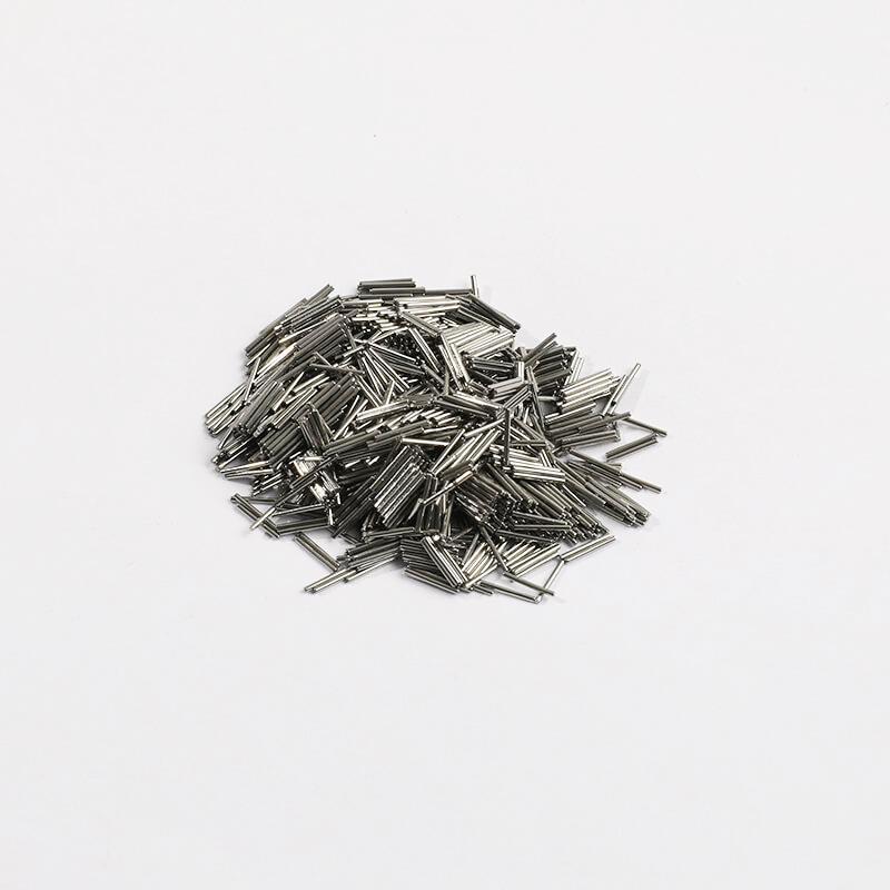
| Media | Best fit | Watch out for |
|---|---|---|
| Dry media: walnut shell and corn cob | Light deburring, drying support and residue removal on parts where moisture carryover is the governing concern. | Slower cutting, generates dust requiring extraction, and its condition and moisture content must be controlled to stay repeatable. |
| Ceramic media, angle-cut and triangular shapes | Heavier deburring and edge blending on steel, stainless and titanium parts with accessible corners and recesses. | Wears down and changes effective size class, generates sludge, and can chip or over-round thin sections and soft alloys. |
| Steel media for burnishing | Bright, uniform appearance with minimal dimensional change on parts whose geometry must stay as machined. | Presses debris and hard-water deposits into the surface, concentrates energy on thin sections, and carries iron cross-contamination risk. |
| Compound with corrosion inhibitor for sensitive alloys | Aluminium and stainless parts that must not stain or pit during processing and between-stage handling. | Inhibitor does not compensate for hard or chloride-bearing water, and residue left in recesses can mask later inspection. |
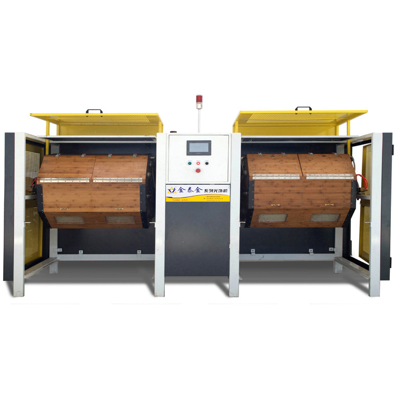
Vibratory finishing is usually the first route to evaluate for aerospace parts because it blends edges and refines surfaces while keeping part-on-part contact moderate and allowing visual access during the cycle. The real differences lie in the chamber: a bowl with a centre column circulates the load continuously, while a tub or long-channel machine moves it more linearly and suits long shafts, tubes and housings that will not turn in a bowl. Drive amplitude, motor setting and the media-to-part ratio decide how much energy reaches the surface, and the machine frame sets the practical part size. For thin-walled or delicate components, ask whether the load can be run in compartments or on fixtures rather than free-tumbling. Also settle unloading and separation early, because a vibratory machine that finishes well but traps media in a closed housing costs more in inspection time than it saves in cycle time.
| Machine route | Where it fits | What it will not do |
|---|---|---|
| Rotary barrel tumbling machine | Gentle, uniform processing of small robust parts in large quantities, such as bushings, spacers and fasteners. | Slow cycles, per-barrel weight limits, and limited access for inspecting or repositioning parts during the run. |
| Dry polishing machine and dryer | Post-wet drying and light dry finishing of parts with blind holes and passages where moisture carryover matters. | Dry media cut slowly, require dust extraction and medium condition control, and forced-air drying must be matched to internal geometry. |
| Disc finishing machine | Fast cycles on flat plates, brackets and robust turned parts with simple geometry. | High energy risks edge roll, distortion of thin sections and part-on-part marking; part size is bounded by the working gap. |
| Magnetic finishing machine | Small precise parts with internal edges and recesses that loose media cannot enter, using small pins or needles. | Bounded by part size and mass, by workpiece material attraction to the pins, and by the need to retrieve residual pins. |
Vibratory, barrel and centrifugal processes remove material at edges far faster than on adjacent faces, so an edge will keep rolling after the face has stopped changing. The defect is not visible damage but a dimension: a radius that has grown past the specified limit, a chamfer that has become a round, or a break edge that has disappeared. Fatigue-critical holes, seal grooves, thread entry chamfers and fastener bearing faces are where the consequence is greatest, because an over-rounded edge reduces bearing area and alters the stress path. Check by establishing the pre-finish edge state and measuring the finished state with radius gauges, an optical comparator or a cast impression, ideally at the same clock positions on several parts. Control it with media size class, cycle time, energy setting and, where limits are tight, a distinct edge operation instead of the bulk cycle.
| Failure mode | Likely cause | How to catch it |
|---|---|---|
| Thread entry chamfer rounded away or thread crests burnished | Unmasked threaded features run in a burnishing or high-energy cutting load. | Gauge the thread with the buyer's own gauge and inspect the entry chamfer under magnification against the recorded pre-finish condition. |
| Dark or heat-tinted patch following the media flow | Lean compound concentration or restricted flow, letting metal fines and heat build up in the working mass. | Compare against the agreed appearance master under fixed lighting and check the measured compound concentration and flow rate recorded for the batch. |
| Edge radius grown past the drawing limit | Cycle time, energy setting or media size class allowing continued edge removal after the adjacent face has stabilised. | Compare the recorded pre-finish edge state with the finished state using radius gauges, an optical comparator or a cast impression at fixed positions. |
| Dimensional drift on a close-tolerance bore or spigot | Total removal accumulating over a long cycle or repeated passes without a start-of-run measurement on a critical feature. | Measure critical dimensions on the first part and at defined intervals through the batch, keeping the process effect separate from incoming variation. |
Osaka retains a broad manufacturing base rather than a single dominant sector. The city's 2020 industrial survey counts 4,879 manufacturing establishments with four or more employees, 112,970 workers and 3,574.7 billion yen of manufactured goods shipments, and reports that metal products manufacturing is the largest single industry by establishment count, followed by printing and allied industries and by production machinery. By value of shipments the leading industries are chemicals, steel and metal products, which together account for 39.0 per cent of the total; within the year's changes, electronic parts and devices, transport equipment and food all grew. Osaka Port is the city's international freight gateway, and the city's economic strategy bureau runs industrial promotion and SME support functions.
The nearest part of that base to this brief is machinery: Osaka's industrial survey reports that metal products manufacturing is the largest industry by establishment count (994 establishments, 20.4 per cent in the 2019 survey) and that production machinery is the third largest, the three leading industries accounting for 43.1 per cent of establishments.
Osaka's mix is heavy in metal products, production machinery, steel and chemicals, and metal products alone account for about a fifth of all manufacturing establishments, most of them small. That structure puts deburring and edge control at the interface between many small machining, pressing and fabrication shops and their customers, where a written edge or roughness limit prevents disputes at incoming inspection.
With most Osaka metal-products firms small and specialised, a buyer should define who measures the burr or edge limit and with what instrument, since the supplier may own the machine but not a metrology standard.
Freight context: Port of Osaka (大阪港), including its container terminals, administered by the Osaka Port Authority. Osaka City publishes the Port of Osaka's annual port statistics, including the 2024 port situation report, vessel entry tables and container terminal data, and runs the port through its port authority alongside city-led logistics promotion. Customs clearance for the Osaka area is handled by Osaka Regional Customs.
Chinese industrial machinery entering Japan is classified under the Customs Tariff Law, whose harmonised schedule sets the classification and the General Rate; the Temporary Tariff Measures Law sets a Temporary Rate for certain products, and where the WTO rate or an EPA rate for the goods is lower, that lower rate is applied. The applied rate therefore depends on the exact commodity code, and on whether an economic partnership agreement covers the goods and their origin, so a landed-cost figure has to be confirmed against the specific machine before it is quoted. Japan Customs' monthly country table for August 2026 records exports to China of 1,809,133 million yen and imports from China of 2,361,239 million yen, the largest single-country line in the Asian table, with imports from China up 22.5 per cent year on year.
The customs authority is Japan Customs, the Customs and Tariff Bureau of the Ministry of Finance, with regional customs at Tokyo, Yokohama, Nagoya, Osaka and Kobe. Any person importing goods must declare them to the Director-General of Customs and obtain an import permit after examination and payment of customs duty and consumption tax. The declaration is normally filed by the importer or by a customs broker acting as proxy, on a triplicate import (customs duty payment) declaration form (Customs form C-5020) supported by the invoice, the bill of lading or air waybill, a certificate of origin where a WTO rate applies, certificates of origin for preferential rates, packing lists and freight and insurance documents where required, plus any licence or certificate demanded by laws other than the Customs Law. More than 90 per cent of import procedures are computerised. A JIS Mark certificate is a separate, voluntary third-party scheme; foreign exporters are eligible to apply, and certification bodies must comply with ISO/IEC 17065.
SurfacePolish supplies from Xiamen, China. The buyer's own destination rules, conformity marking, tariff classification and documentation responsibilities stay with the buyer; confirm them against the authorities named above before ordering.
Acceptance begins with a written decision about how many parts are examined and which one is the reference. A workable plan names the sample size per batch, the inspection frequency, the measurement locations and the person responsible for accepting or rejecting. A first article should be fully inspected against the drawing and the agreed requirements, then retained as the physical reference for later comparison, because appearance memory is unreliable across shifts. For lower-volume aerospace work, the sensible pattern is to inspect the first part of each batch completely, examine a defined sample through the run and inspect critical features on every part when the feature is safety-relevant or the process is not yet stable. Fix these rules before the first production batch, when there is still room to argue about the requirement rather than about the parts.
Send parts that represent the production condition, not the best examples from a setup rack. Include the part with the tightest internal feature, the thinnest wall and the most difficult edge, because those features decide the process more than the largest flat face does. Provide the material and heat treatment, the drawing requirements you can share, and a marked-up photograph that identifies the features which must not change and those which must. Include one or two parts in the incoming condition with no prior finishing, plus, where available, a part finished the way you want the result to look. State the batch size and how parts are separated in your own shop, since load pattern affects outcome as much as media choice. Where a family has variants, send the extremes of the family rather than a middle case.

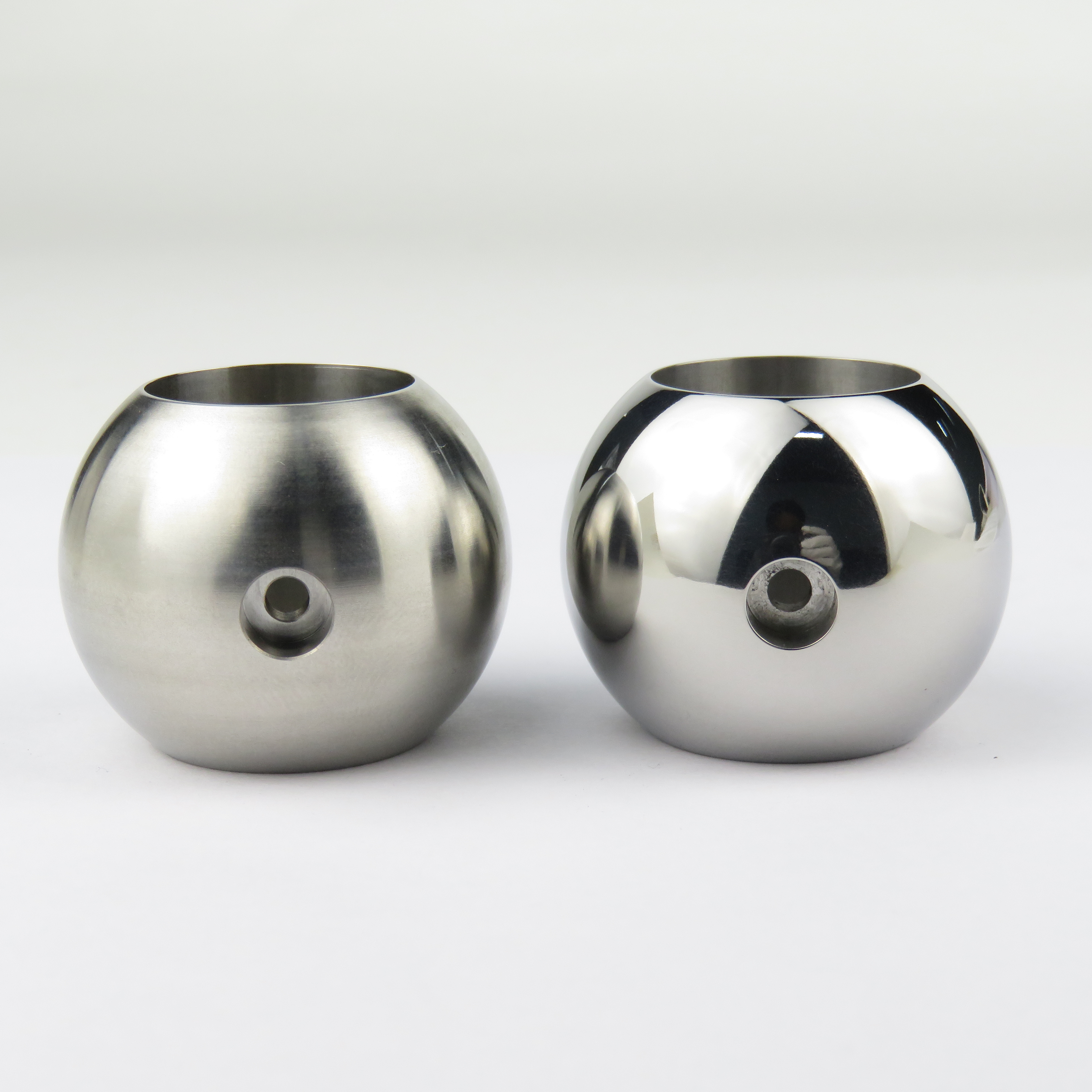
Record the edge condition before finishing, set the allowable band in writing, and measure afterwards with radius gauges, an optical comparator or a cast impression at fixed positions. Because edges lose material much faster than adjacent faces, the cycle continues to change them after the face has stabilised, so time, energy setting and media size class are the controlling variables. If the band is tight, plan a separate edge operation rather than relying on a bulk cycle. A sample trial can show how a named edge behaves under two media classes on the parts you send, which gives your engineering group data to set a limit instead of an opinion.
Send parts in the production condition, including the case with the thinnest wall, tightest internal feature and most difficult edge, not a convenient spare. Include material and heat treatment data, the drawing requirements you can share, and a marked-up photograph showing features that must not change. Add one part in the incoming condition and, if available, one finished the way you want the result to look. State the batch size and how you separate parts in your own shop. International shipments should be declared for temporary processing with a parts list, and buyers in Japan can ask us for a packing list format before dispatch.
No. A part can look bright and uniform while carrying embedded media fragments, a smeared surface layer, dried compound residue in a recess or an edge that has rolled past its limit. Acceptance needs measurement at defined locations, edge checks where edges are specified, and cleanliness checks of internal features, all recorded against the drawing requirement. Define appearance with a physical master or a calibrated image set under fixed lighting and magnification, since adjectives are not criteria. For a buyer in Japan, the practical rule is that appearance is one input among several, and no appearance result on its own establishes fitness for a regulated application.
Use Osaka, Japan as the destination on the enquiry and state whether the deliverable is equipment, media and compound, a representative sample review or a line concept. A destination does not imply local stock, a local service point or a local delivery time.
Osaka buyers reference JIS, maintained by the Japanese Industrial Standards Committee, with mechanical engineering and ferrous materials divisions covering the city's metal-products and machinery output and the JIS Mark scheme available for third-party certification. Acceptance of a finished surface is normally tied to the customer's drawing and incoming inspection rather than to a single national finishing standard.
Sources were retrieved on 2026-09-29 and describe the local industrial and trade context only. They do not evidence any SurfacePolish project, shipment, installation or service in Osaka.
The buyer needs to remove machining burrs and blend edges without rounding the flange or lodging media in the blind tapped holes.
Send the material, dimensions, approximate weight, batch quantity, the incoming condition and photographs of the difficult features. Mark which features must not be contacted by media and state how the result will be inspected. This form carries source reference PSEO-0811; quote it if you prefer an additional manual reference.
Open the SurfacePolish enquiry form Email a prepared enquiry
No price, lead time, certification or result is promised here. Confirm whether a sample trial is available for the specific part and what the trial can and cannot show.
Page PSEO-0811 · revised 2026-09-29 · cross-border equipment, media and scoped sample review. City context is sourced and cited above.
Use this local checker to identify missing part and inspection information. It prepares a technical-review brief; it does not approve a machine, process recipe or production result.
Complete the part details to prepare a review brief.
Email : info@surface-polish.com


 IPv6 network supported


 +86-592-2381506