A process engineer in Tokyo, Japan is finishing a stainless valve body for aerospace components and needs an external finish without disturbing a lapped sealing face or leaving media at the cross-drilled intersections. SurfacePolish is a cross-border supplier of finishing machines and consumables running a free sample trial; parts are sent in, run against an agreed feature list, and returned with observations on the parts tested rather than a performance guarantee. This brief is written for a buyer in Tokyo working on aerospace components; it describes equipment, media and a scoped sample review, not a local polishing service.
Does the compound chemistry family create a hydrogen, staining or residue risk for this alloy and heat treatment, and who verifies that?
What edge condition is actually specified at each critical location, and which machine and media combination can hold inside that band?
Which datum and mating surfaces carry assembly geometry, and is a flatness or fit check required on them after finishing?
Datum and mating surfaces constrain the whole finishing decision because they establish assembly geometry. Media contact on a datum face can shift hole position, introduce local flatness variation or change a press-fit condition, and none of that is visible in ordinary shop inspection. Identify on the drawing which surfaces are datums and which mate with another part, then treat the finish callout on those surfaces separately from cosmetic areas. A part may tolerate a brighter appearance on an outboard face while its bolted flange must simply remain flat within its stated requirement. Protection strategy follows the same logic: a datum is often masked, fixtured against a support or finished with a lighter medium rather than with the same blend as the rest of the part. Discuss finish location with the designer before promising a blanket surface condition.
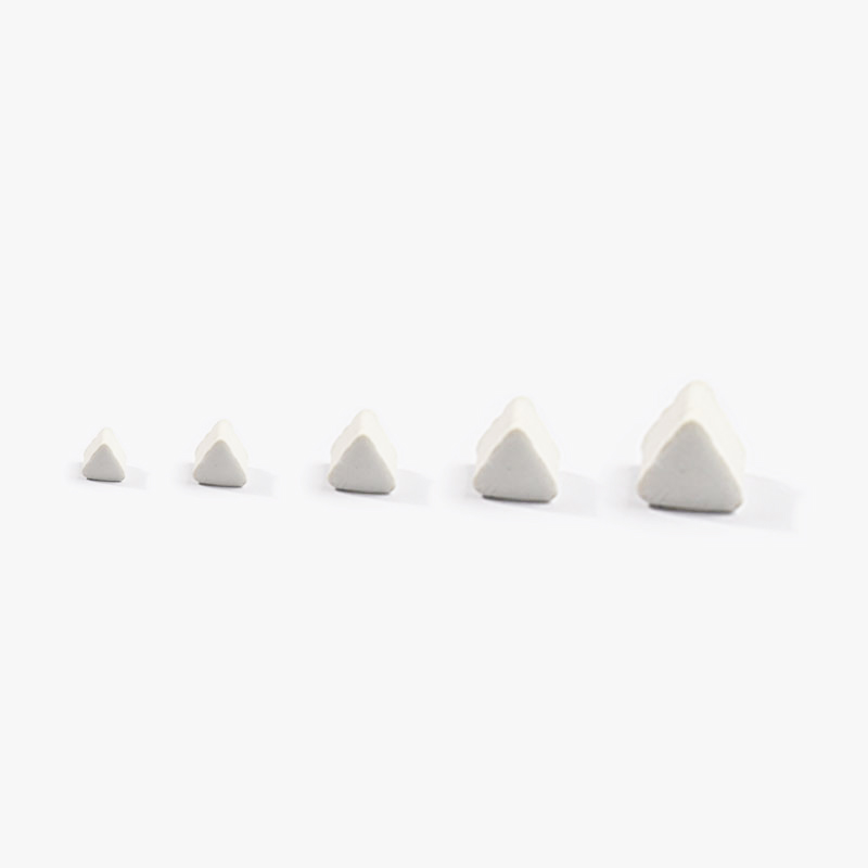
Plastic media removes material gently through a light cutting and burnishing action and is the usual first candidate for aluminum, thin-wall sections and parts where a soft surface must not be scored. Its lower density and hardness mean it conforms rather than cuts deeply, which protects delicate features but also makes it slower and less effective in deep recesses and tight radii where a harder medium is needed to reach. Wear behaviour is different from ceramic: plastic media deform, lose sharpness and load with metal fines, so a blend can look intact while its cut rate has collapsed. Dry media in the same family, such as walnut shell and corn cob, is used for light deburring and drying support rather than for aggressive stock removal. Choose plastic when feature preservation dominates and the required removal is light; verify by measuring the same locations before and after rather than judging by appearance.
| Media | Best fit | Watch out for |
|---|---|---|
| Mildly acidic or chelated brightening compound | Brightening certain stainless grades where the buyer's specification permits that chemistry family. | Not appropriate where hydrogen uptake is a concern on high-strength steel, and requires close pH control and good rinse water quality. |
| Dry media: walnut shell and corn cob | Light deburring, drying support and residue removal on parts where moisture carryover is the governing concern. | Slower cutting, generates dust requiring extraction, and its condition and moisture content must be controlled to stay repeatable. |
| Alkaline detergent compound | General cleaning and suspension of removed material on steel, stainless and aluminium where neutral to alkaline chemistry suits the alloy. | Running lean causes loading, heat and discoloration; running rich causes foam and residue that lodges in blind features. |
| Plastic media, cones and triangles | Gentle cutting on aluminium, thin-wall sections and surfaces that must not be scored. | Deforms and loads with metal fines so cut rate falls while the blend still looks intact; ineffective in deep recesses and tight radii. |
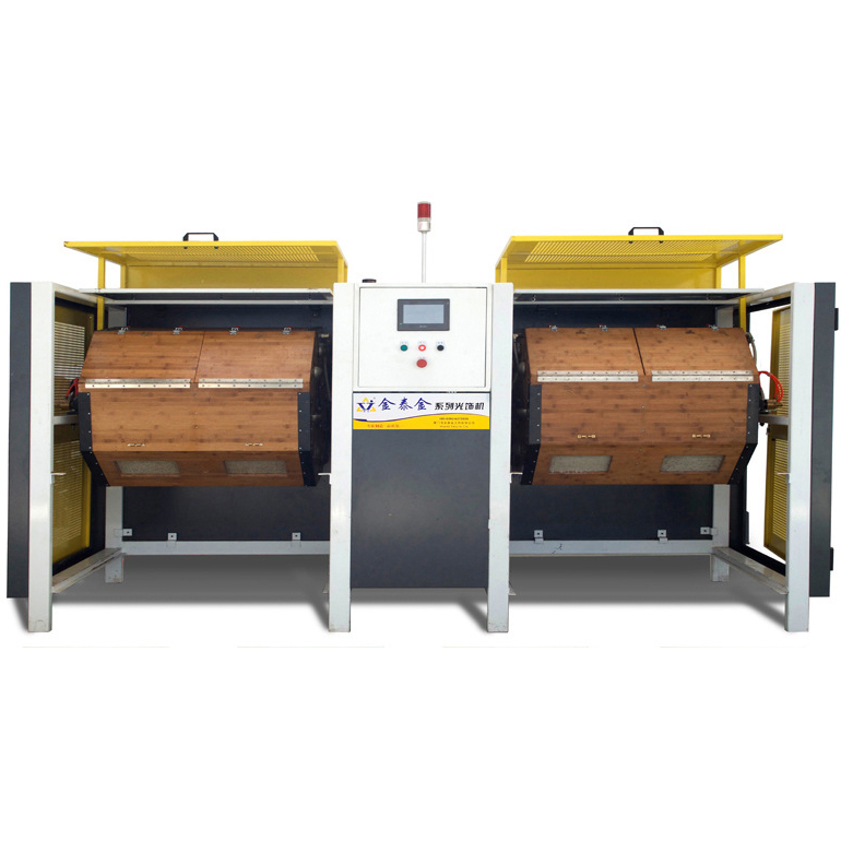
Disc finishing machines generate fast cycles by driving media and parts between a rotating disc and the chamber wall, which raises energy at the part surface and shortens the time needed to blend an edge or refine a face. That energy is the trade: flat plates, simple brackets and robust turned parts finish quickly and evenly, while assemblies with thin sections, brazed joints, unsupported flanges or already-tight edge limits can suffer edge rolling, local distortion or part-on-part marking. Geometry limits are real, since a part that is larger than the working gap or too light to stay in the media stream will not be processed predictably. The route deserves evaluation when removal rate and cycle time dominate and the part is simple and robust. Where a part is complex or expensive, disc finishing is more often a stage for one defined face than a whole-part answer.
| Machine route | Where it fits | What it will not do |
|---|---|---|
| Vibratory finishing machine, bowl type | General edge blending and surface refinement on medium-sized parts with a continuous, visible load. | Part size is capped by chamber geometry, and thin or delicate parts may need compartments or fixtures to limit part-on-part contact. |
| Disc finishing machine | Fast cycles on flat plates, brackets and robust turned parts with simple geometry. | High energy risks edge roll, distortion of thin sections and part-on-part marking; part size is bounded by the working gap. |
| Centrifugal barrel finishing machine | Short cycles on small, hard, robust parts where high pressure at the part-media interface is acceptable. | High energy transfers into thin walls and fixtures and wears liners; part size and barrel geometry bound what can be run. |
| Dry polishing machine and dryer | Post-wet drying and light dry finishing of parts with blind holes and passages where moisture carryover matters. | Dry media cut slowly, require dust extraction and medium condition control, and forced-air drying must be matched to internal geometry. |
Impingement shows up as a local patch of heavier material removal, a gouge or a flattened edge where media or another part struck the surface with too much energy. On aerospace work it appears most often on thin webs, long unsupported sections, sharp external corners and parts run at too high an amplitude in a lightly loaded chamber. The cause is rarely the medium alone; it is the combination of energy setting, media size and mass, load volume and the freedom of parts to move against each other. Check for it by inspecting known vulnerable features under magnification before and after, by photographing under raking light rather than diffuse light, and by comparing the same feature across several parts from the load. Mitigation follows the diagnosis: reduce amplitude, add media, compartmentalise or fixture the part, or move the operation to a gentler route.
| Failure mode | Likely cause | How to catch it |
|---|---|---|
| Dimensional drift on a close-tolerance bore or spigot | Total removal accumulating over a long cycle or repeated passes without a start-of-run measurement on a critical feature. | Measure critical dimensions on the first part and at defined intervals through the batch, keeping the process effect separate from incoming variation. |
| Thread entry chamfer rounded away or thread crests burnished | Unmasked threaded features run in a burnishing or high-energy cutting load. | Gauge the thread with the buyer's own gauge and inspect the entry chamfer under magnification against the recorded pre-finish condition. |
| Impingement marks or gouges on thin webs and sharp corners | Excess amplitude or speed with too little media in the chamber, or parts free to strike each other in an under-filled load. | Inspect the vulnerable features under magnification before and after, photograph under raking light, and compare the same feature across several parts from the load. |
| Dark or heat-tinted patch following the media flow | Lean compound concentration or restricted flow, letting metal fines and heat build up in the working mass. | Compare against the agreed appearance master under fixed lighting and check the measured compound concentration and flow rate recorded for the batch. |
Tokyo's manufacturing is concentrated in the eastern wards rather than spread evenly across the metropolis. Ota City states that the number of manufacturing establishments in Tokyo is largest in Ota, and describes itself as a metalworking town of small and medium firms; about 3,500 manufacturing establishments are counted there (2021 Economic Census). The ward's core 'base technologies' are cutting, pressing, forming, grinding, casting, forging and plating, and it reports that these support fields extending from automobiles to medical equipment and aerospace, with Naka-Ikegami concentrating industrial equipment makers and Omori-nishi concentrating electro-mechanical manufacturers. Multi-product, small-lot production and prototyping and R&D work are named as strengths of the district.
For this brief the relevant part of that base is aerospace: Ota City states that the ward's base technologies support fields 'from automobiles to medical equipment and aerospace', and that local firms have entered aerospace and electronics.
Ota's base-technology list explicitly includes grinding and plating, and the ward reports that its firms are specialised by process step and linked across steps to achieve high-precision, compound machining and short lead times. In a district built on multi-product, small-lot work and prototyping, deburring, edge condition and pre-plating surface cleanliness are process-step decisions rather than finishing afterthoughts, because each downstream firm in the chain inspects what the previous step delivered.
Because Ota's supply chain is organised by process step, a Tokyo buyer should decide first which step owns the edge condition — the machining shop, the grinder or the plater — and specify burr and edge limits on the drawing so the requirement is not re-negotiated at each hand-off.
Freight context: Port of Tokyo (東京港) — container terminals including Oi, with the port's hinterland covering the 40-million-person Greater Tokyo area, Shinetsu and southern Tohoku, Haneda Airport (羽田空港, Tokyo International Airport), located in Ota City's waterfront. The Port of Tokyo is described by the Tokyo Metropolitan Government as an urban general port handling goods needed by the metropolis' industry and residents, with imports accounting for two thirds of cargo volume by in/out direction. The Tokyo Metropolitan Government reports Port of Tokyo container throughput of 4.86 million TEU for 2025, 3.3 per cent above 2024, so containerised receipt of machines and dispatch of sample parts runs through the same port complex.
Chinese industrial machinery entering Japan is classified under the Customs Tariff Law, whose harmonised schedule sets the classification and the General Rate; the Temporary Tariff Measures Law sets a Temporary Rate for certain products, and where the WTO rate or an EPA rate for the goods is lower, that lower rate is applied. The applied rate therefore depends on the exact commodity code, and on whether an economic partnership agreement covers the goods and their origin, so a landed-cost figure has to be confirmed against the specific machine before it is quoted. Japan Customs' monthly country table for August 2026 records exports to China of 1,809,133 million yen and imports from China of 2,361,239 million yen, the largest single-country line in the Asian table, with imports from China up 22.5 per cent year on year.
Documentation and technical communication are Japanese-language in practice: JISC states that the documents submitted for JIS certification-body accreditation must be written in Japanese, and drawings, inspection sheets and purchase specifications from Japanese buyers are normally issued in Japanese. Import declarations are filed in triplicate and importers commonly use licensed customs brokers, so the commercial invoice, packing list and origin documents must be complete and consistent with the declared commodity code. As general industry practice in Japan, industrial buyers qualify a supplier on documentation, quality-management evidence and a defined inspection standard before volume orders, and expect a named Japanese-speaking contact for technical and commercial follow-up.
SurfacePolish supplies from Xiamen, China. The buyer's own destination rules, conformity marking, tariff classification and documentation responsibilities stay with the buyer; confirm them against the authorities named above before ordering.
Appearance should be defined by an agreed physical master or a calibrated image set viewed under specified lighting and magnification, because written adjectives such as bright or uniform are not acceptance criteria. Beside appearance, insist on the checks that reflect how the part actually works. A seal land is checked for sealing condition, a bearing seat for fit and contact pattern, a sliding surface for freedom from raised material and a threaded feature for gauge entry. Edges are measured rather than viewed, using radius gauges, an optical comparator or a cast impression against the recorded pre-finish state. Functional checks should be performed with the buyer's own gauges where the buyer owns the acceptance decision, and the results recorded against the specified requirement instead of a pass or fail opinion. Where a check damages a part, define it as a sampling check on dedicated parts.
Scale-up fails more often on bookkeeping than on metallurgy. Define the load before the first production batch: the range of part count or weight, how parts are separated, whether families may be mixed, and by what rule a load is split when a different feature set arrives. Record the cycle as it was actually run, including the media blend, compound concentration measured at the machine, water source, run time and the reason for any deviation, because a deviation that is not written down reappears as an unexplained appearance change. Set a media maintenance plan with a screening interval, a make-up rate by weight, a bath cleaning routine and a replacement trigger based on measured condition rather than on a calendar alone. Media wear changes the process gradually, so the record is the only way to notice drift before parts are affected.

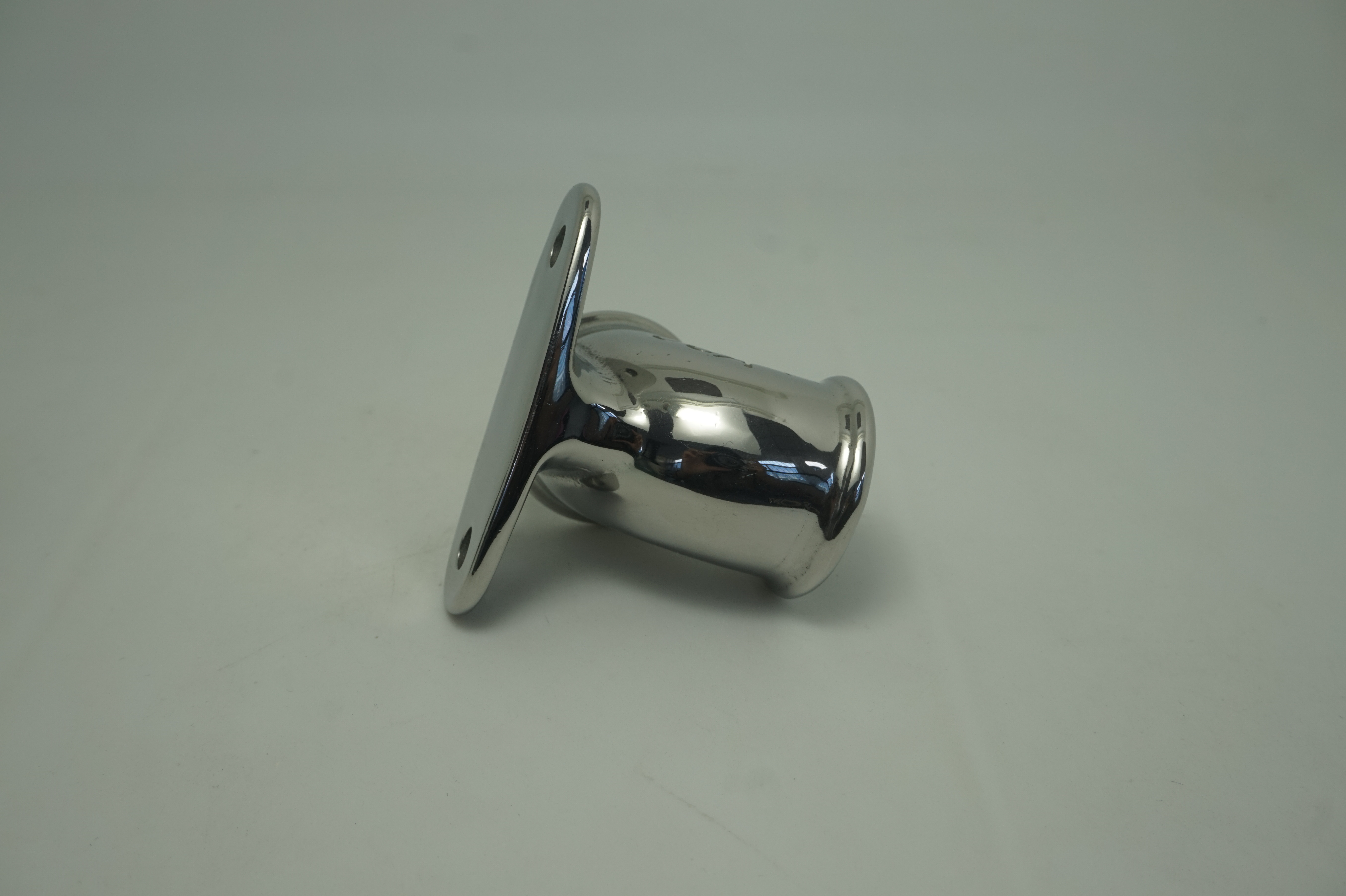
Record the edge condition before finishing, set the allowable band in writing, and measure afterwards with radius gauges, an optical comparator or a cast impression at fixed positions. Because edges lose material much faster than adjacent faces, the cycle continues to change them after the face has stabilised, so time, energy setting and media size class are the controlling variables. If the band is tight, plan a separate edge operation rather than relying on a bulk cycle. A sample trial can show how a named edge behaves under two media classes on the parts you send, which gives your engineering group data to set a limit instead of an opinion.
SurfacePolish is not a local polishing shop and has no branch, dealer or technician presence in Tokyo or anywhere else outside its own factory. What is offered is cross-border supply of finishing machines and consumables, a scoped discussion of a finishing line concept, and a free sample trial in which representative parts are shipped to the factory, processed and returned with observations and a proposed media and cycle direction. Buyers who need on-site processing should source that locally. Buyers building an in-house finishing capability can use the trial to choose equipment and media for their own line.
Specify the location, the evaluation length and cutoff, the filter, and whether the requirement is a maximum or an average, then keep that setup unchanged for every batch and comparison. Readings taken with different cutoffs on the same surface will not agree, and readings on interrupted or curved surfaces such as fillets or cast skins need a setup designed for them. Record the instrument and its calibration status with the results. When you compare a trial part from Xiamen with your production parts, Japan and China, use one instrument and one setup so the difference you are reading is the process, not the measurement.
Use Tokyo, Japan as the destination on the enquiry and state whether the deliverable is equipment, media and compound, a representative sample review or a line concept. A destination does not imply local stock, a local service point or a local delivery time.
Tokyo buyers work to JIS, maintained by the Japanese Industrial Standards Committee, with the mechanical engineering and ferrous materials divisions covering machined metal parts; the JIS Mark scheme provides third-party product certification, and foreign exporters are eligible to apply. Drawings and inspection sheets issued by the customer, not a generic finishing standard, define the acceptance criteria for burrs, edge radius and surface texture.
Sources were retrieved on 2026-09-29 and describe the local industrial and trade context only. They do not evidence any SurfacePolish project, shipment, installation or service in Tokyo.
The buyer wants a uniform external finish while keeping the sealing face flat and confirming that no media remains in the intersecting passages.
Send the material, dimensions, approximate weight, batch quantity, the incoming condition and photographs of the difficult features. Mark which features must not be contacted by media and state how the result will be inspected. This form carries source reference PSEO-0801; quote it if you prefer an additional manual reference.
Open the SurfacePolish enquiry form Email a prepared enquiry
No price, lead time, certification or result is promised here. Confirm whether a sample trial is available for the specific part and what the trial can and cannot show.
Page PSEO-0801 · revised 2026-09-29 · cross-border equipment, media and scoped sample review. City context is sourced and cited above.
Use this local checker to identify missing part and inspection information. It prepares a technical-review brief; it does not approve a machine, process recipe or production result.
Complete the part details to prepare a review brief.
Email : info@surface-polish.com


 IPv6 network supported


 +86-592-2381506