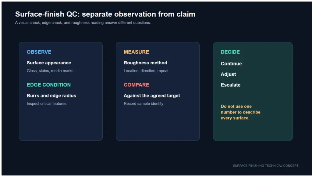
A finishing trial is difficult to approve when “looks smoother” is the only result. Burr removal, edge preservation and surface texture are different questions, so they need separate checks. This practical measurement plan helps buyers and suppliers compare incoming parts with trial samples without inventing a universal acceptance limit.
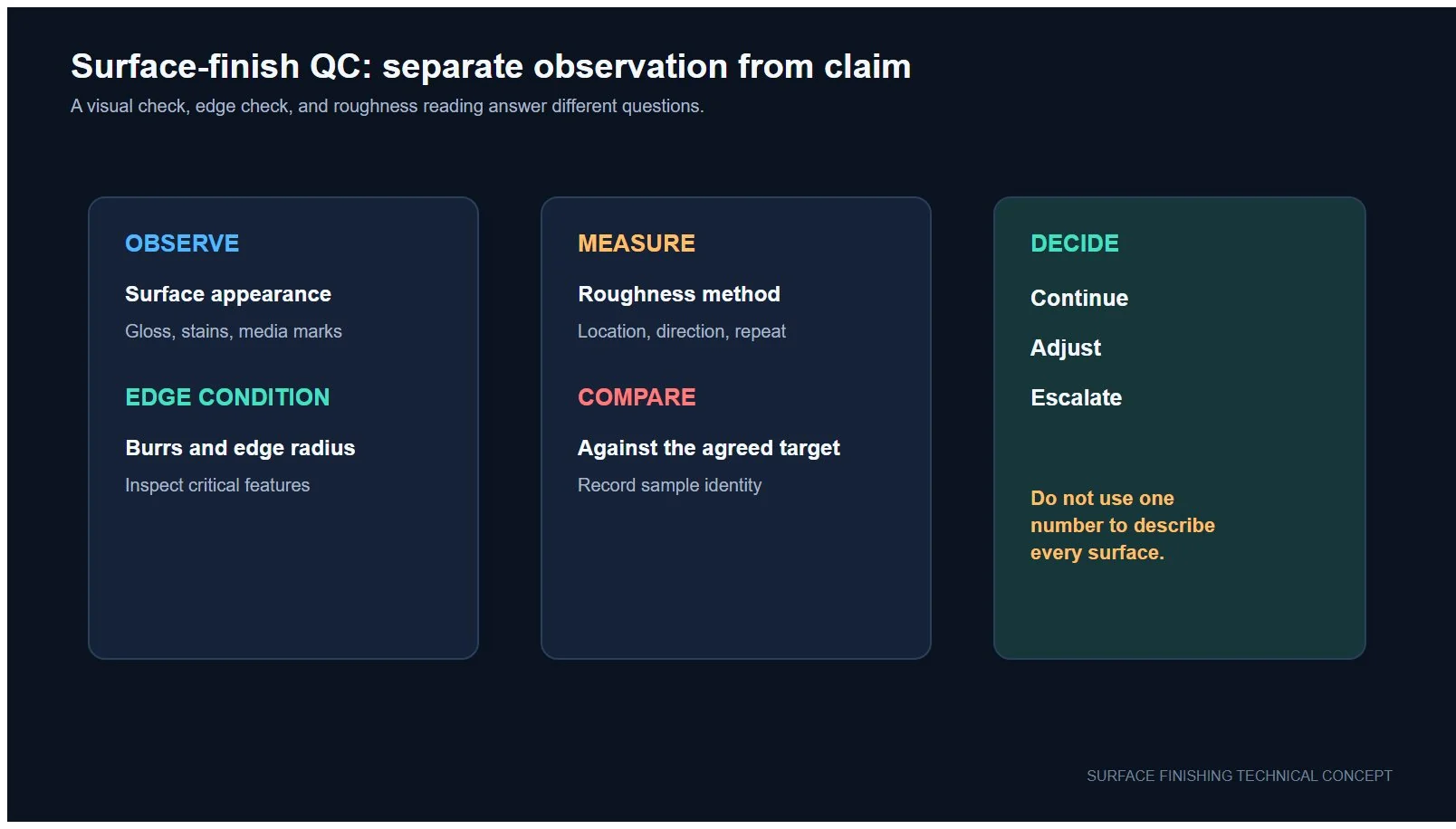
Conceptual measurement workflow. The drawing does not represent a measured customer result.
Mark the features that affect fit, sealing, coating, assembly or handling. A burr at a cross-hole may need a height check; a functional edge may need radius or profile comparison; a sealing face may need a specified surface-texture parameter. Do not replace the drawing requirement with a generic “polished” target.
Use a defined viewing direction and a repeatable optical or profile method. Record the feature location, magnification or instrument, lighting, fixture and whether the result is a maximum reading, a profile value or a pass/fail visual rule. Photograph the same feature before and after the trial when practical.
Measure the edge where function requires control. Depending on the drawing and access, this may be an edge radius, chamfer dimension or profile comparison. Record the datum, section or inspection plane so the next sample is measured in the same place. Surface roughness cannot substitute for this geometry check.
Report the specified parameter, such as Ra or another drawing-defined profile parameter, together with the instrument and method settings. NIST documentation shows that stylus geometry, filtering, sampling and calibration affect a surface-profile measurement. Keep the method and measurement direction consistent between the incoming and processed samples.

Record the method with the number; do not compare isolated readings from unknown settings.
| Field | What to record | Why it matters |
|---|---|---|
| Part and feature | Part ID, drawing revision, feature ID and inspection location | Prevents measurements from drifting to an easier area |
| Incoming condition | Burr direction, visible damage and baseline readings | Separates process change from incoming variation |
| Burr method | Optical/profile method, fixture, direction and reporting rule | Makes the residual-burr decision repeatable |
| Edge method | Radius, chamfer or profile method and datum | Checks whether functional geometry was preserved |
| Texture method | Parameter, instrument, tip or optical method, filter/cutoff, evaluation length and direction | Lets before-and-after texture readings be compared |
| Sampling | Number of parts, locations per part and handling rule | Avoids approving a batch from one convenient point |
| Decision | Drawing limit or agreed trial criterion, result and disposition | Creates an auditable release record |
NIST comparisons show that optical and stylus roughness measurements can disagree on some surfaces. If the incoming part is measured with one method and the trial sample with another, treat the difference as a method change until a correlation study shows otherwise. The safest supplier comparison uses the same verified instrument family, settings, direction and locations.
Retain an identified incoming sample and an approved processed sample when the program allows it. A fixture, marked inspection zone or drawing callout helps the supplier return to the same location. For complex parts, use a small feature map rather than averaging unrelated faces.
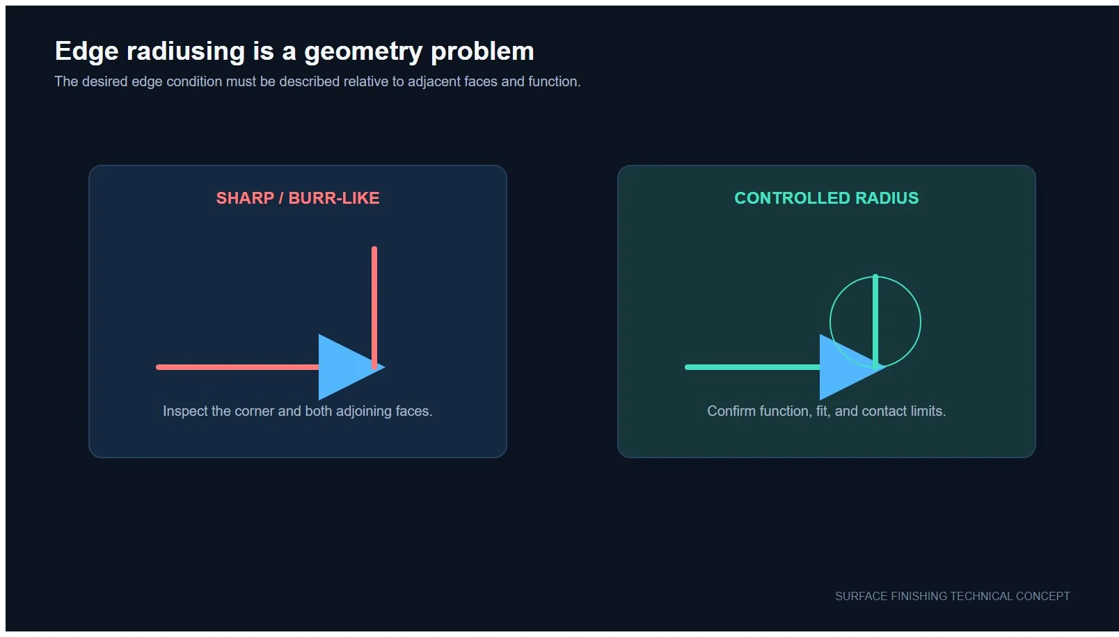
Edge change is a geometry question and should be checked independently from surface texture.
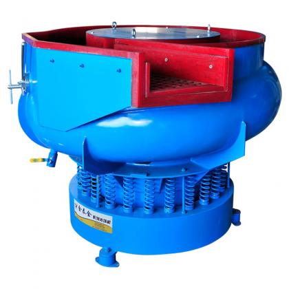
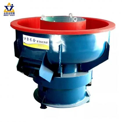
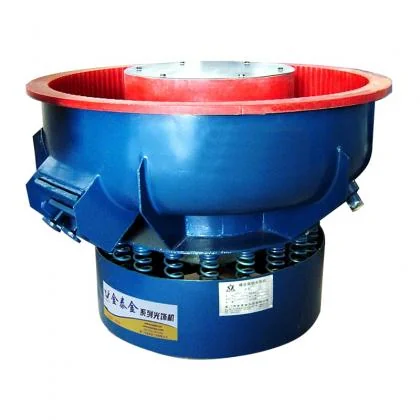
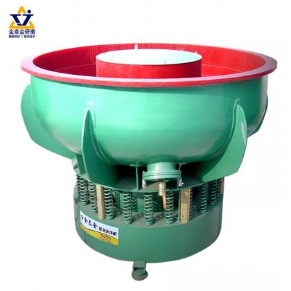
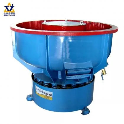
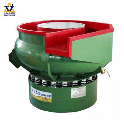
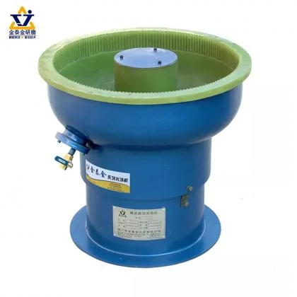
Record the machine family, media, compound, water condition, load, time and inspection interval with the measurement result. The mass-finishing sample trial record provides a worksheet for this context. For wet-process variables, use the water and compound control trial method. Buyers still selecting equipment can review the vibratory finishing machine guide.
Before shipping parts, provide the drawing revision, incoming condition, protected features, required measurement method and the acceptance rule. If the method is not yet fixed, ask the supplier to propose a trial measurement card for approval before processing.
Need a documented finishing trial? Send the part material, geometry, incoming burr condition and drawing-based inspection requirements. The trial plan should be confirmed against the real part before any process result is promised.
Email : info@surface-polish.com


Burr height is the distance the raised material extends above the intended edge. It is measured on a section or with a profilometer trace taken across the edge, and it is the most direct way to show whether a deburring process actually removed the burr.
Ra is an average roughness value taken along a measured trace. It describes the general texture of a surface but says nothing about whether a burr remains or whether an edge has been rounded. Ra alone is not a deburring specification.
Edge change is measured by comparing the edge profile before and after processing, usually as an edge radius or a chamfer dimension. It requires a reference measurement from the starting condition, because the change is the difference, not the final value.
Ra averages the profile, so two surfaces with the same average can have different peak heights, scratch patterns or edge conditions. Visual appearance and functional behaviour are often decided by those features rather than by the average.
Measure the starting condition before processing so there is a baseline, and measure the finished parts using the same method and instrument. Without a baseline, a finished value cannot be interpreted.
Answers are directions to test on a sample part, not validated results for a specific component.
 IPv6 network supported



 +86-592-2381506