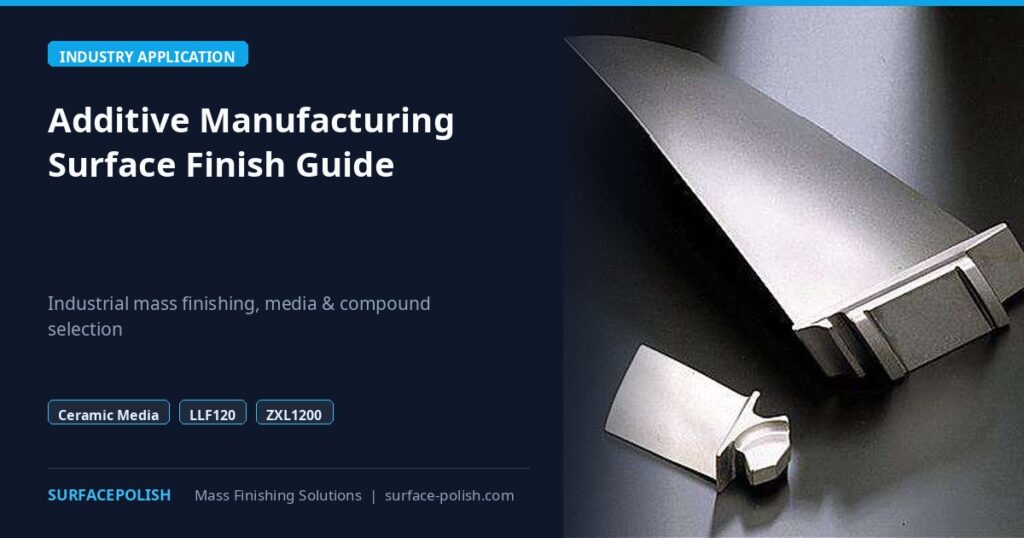
Additive Manufacturing Surface Finish: Removing DMLS Powder Sintered Roughness With Mass Finishing

Additive manufacturing engineers and post-processing leads seeking a reliable additive manufacturing surface finish on DMLS, SLM, and binder-jet metal parts face a far rougher starting surface than traditional CNC machining. Laser powder-bed fusion (304/316 stainless steel, Ti-6Al-4V titanium, and AlSi10Mg aluminum) leaves partially sintered satellite powder spheres, stair-step build layers, and sharp support-removal witness marks across every face. Attempting to burnish raw printed parts straight in 304 balls or high-alumina spheres merely shines bumpy sintered peaks without leveling valleys. Pairing aggressive Stage 1 high-frequency ceramic cutting (LC10)—or resin plastic cones (LC10) on soft printed aluminum—with Stage 2 ball burnishing and heated 35A/70A drying transforms rough 3D-printed metal into smooth, functional, mirror-ready hardware.
Why 3D-Printed Metal Needs Two-Stage Mass Finishing

Breaking Down Partially Sintered Satellite Powder and Layer Stair-Steps
Unlike billet CNC surfaces with uniform directional cutter marks, DMLS and SLM parts carry millions of microscopic partially melted metal spheres fused onto outer skins alongside coarse support-structure stubs. Stage 1 abrasive mass finishing shears away loose satellite spheres and grinds down high layer ridges isotropically, exposing dense solid metal underneath before any Stage 2 brightening begins.
Protecting Thin Lattice Walls and Delicate 3D Features
Modern generative-design aerospace brackets and medical cages combine thick structural bosses with thin delicate ribs or lattice struts. Overloading fragile 3D-printed parts into an aggressive ZL bowl with heavy stones bends thin walls! Adjust tumbler media ratio cushions generously, dial vibratory motor counterweight lead angles down, or use divided ZXL linear troughs and LLB50 centrifugal disc finishers to protect thin printed geometry.
Alloy-Specific Media Selection (316 vs. Ti-6Al-4V vs. AlSi10Mg)
Never run one single media charge across every 3D-printed alloy! Hard 316 stainless and 17-4PH printed parts require fast-cut then fine-cut high-frequency ceramic stones (LC10) followed by 304 stainless balls (JTJ20/JTJ60); Ti-6Al-4V titanium requires strictly iron-free high-frequency ceramic (LC10) followed by iron-free high-alumina spheres (HM3/JTJ50); and softer AlSi10Mg printed aluminum requires lightweight resin-bonded synthetic plastic cones (LC10) followed by high-alumina spheres (HM3/JTJ50).
Removing Residual Loose Powder Before Wet Tumbling Starts
Always depowder and grit-blast or air-blow loose trapped build powder out of internal cooling channels and support pockets before loading wet ZL bowls! Loose titanium or aluminum powder carried straight into wet slurry turns into dense settling-tank sludge rapidly.
| Printed Metal Alloy | Stage 1 Leveling Media & Chemistry | Stage 2 Burnishing Media | Stage 2 SurfacePolish Compound |
Drying & Final Buff |
|---|---|---|---|---|
316 / 17-4PH Stainless |
Fast then fine high-frequency ceramic (LC10) |
304 stainless balls & ball-cones |
JTJ20, JTJ25, or JTJ60 |
RO/soft rinse + 35A/70A + corncob |
Ti-6Al-4V Titanium |
Fine high-frequency ceramic (LC10) |
Iron-free high-alumina spheres |
HM3 or JTJ50 (zero steel balls) |
Soft/RO rinse + 35A/70A spin-dry |
AlSi10Mg Aluminum |
Resin plastic cones (LC10) |
Iron-free high-alumina spheres |
HM3 or JTJ50 |
Soft/RO rinse + 35A/70A spin-dry |
| Printed Carbon / Tool Steel | High-frequency ceramic + LC10 / MC8 |
304 balls (isolated cell) |
JTJ25 / JTJ20 |
Soft rinse + immediate 35A/70A + VCI |
| Intricate Printed Lattices | Small non-lodging ceramic / plastic | OBD-30..100 magnetic pins |
HM3 / JTJ50 fresh bath |
Clean rinse + 35A + warm air blow |
Chemistry, Single-Pass Hydraulics & Peristaltic Compound Dosing

Flushing High Silt Loads With Single-Pass Flow Through
Because DMLS parts shed far more surface mass during Stage 1 roughness leveling than smooth CNC parts, closed-sump recirculation tanks choke into thick metallic mud within hours—stalling cutting speed and causing ceramic media glazing. Always run continuous single-pass flow through mass finishing piped through clean bottom drain slots into a generous multi-baffle settling tank.
Calibrating Peristaltic Compound Dosing & Softened Water
Steady peristaltic compound dosing injects exact compound-LC10 ratios during long Stage 1 leveling cycles so ceramic pores stay sharp and un-glazed, while softened makeup water prevents hard calcium soap-scum during Stage 2 JTJ20/HM3 mirror burnishing. Review our water hardness in mass finishing guide and preventing foam in vibratory bowls guide.
Upstream Cleaning When Printed Parts Undergo CNC Post-Machining
Many 3D-printed aerospace housings and orthopedic implants undergo secondary CNC milling on critical mating faces before mass finishing—picking up emulsifiable coolant and tapping oils. Always run degreasing before vibratory finishing on CNC-post-machined printed parts so cutting oils never glaze ceramic beds.
Keeping 304 Balls & Titanium Cells Strictly Free of Tramp Iron
Never process 316 stainless or Ti-6Al-4V printed parts in bowls, baskets, or MC8 cells shared with carbon-steel parts! Stray iron dust triggers rust blooms on printed stainless and contaminates passive titanium surfaces.
Preventing Media Lodgment & Handling Complex 3D Cavities
Sizing Media Against Internal Channels and Lattice Windows (Non-Lodging)
3D-printed manifolds feature conformal cooling channels, lightening pockets, and lattice windows that trap poorly sized media instantly. Select ceramic, plastic cone, and high-alumina diameters strictly via our non-lodging media sizing guide and screen out worn slivers weekly following our media screening and replenishment SOP.
Using OBD-30..100 Magnetic Polishers for Complex Printed Recesses
When printed jewelry, dental frameworks, or miniature fluidic manifolds carry deep internal corners unreachable by round spheres, short OBD-30..100 magnetic pin cycles (compound-HM3 or JTJ50) brighten tight pockets cleanly—followed by thorough rinsing and inspection to confirm zero trapped pins inside blind channels.
Immediate 35A/70A Spin-Drying & Dry Corncob Wipe Buffing
Porous or rough 3D-printed skins hold rinse water stubbornly unless spun dry immediately in a heated 35, 35A, 70, or 70A centrifugal dryer—blocking flash rust on printed tool steel and calcium drying spots on stainless or aluminum. For optical showcase parts, follow with warm dry corncob buffing (never adding water to dry organic media!). See our centrifugal dryer guide and corncob drying media grades guide.
Protecting Support-Scarred Edges With Controlled Tumbler Media Ratio
Heavy printed stainless or Inconel blocks colliding inside under-filled ceramic beds suffer chipped corners. Maintain generous tumbler media ratio cushions inside reinforced ZL bowls or divided ZXL linear troughs.
Machine Platforms: ZL Bowls, ZXL Troughs, and LLB50/LLF120

Continuous ZL Bowls vs. High-Energy LLB50 / LLF120 Centrifugal Units
Standard ZL circular bowls handle large production volumes of printed brackets smoothly with automated separation and clean spray rinsing, whereas LLB50 centrifugal disc finishers and LLF120 centrifugal barrels generate higher shear force—cutting long Stage 1 DMLS leveling times substantially on small dense batches.
Dividing Large Printed Housings Inside ZXL / L1300–L1800 Troughs
Oversized printed aerospace frames and multi-part manifolds tumble safely inside divided ZXL/L1300–L1800 troughs where compartment dividers prevent heavy printed housings from colliding mid-cycle.
Auditing Polyurethane Bowl Liners Against Coarse Sintered Roughness
Raw DMLS metal parts are far more abrasive against polyurethane walls than smooth stamped washers! Inspect bowl ribs and discharge ramps regularly using our polyurethane bowl liner replacement guide.
Clean Separator Spray Rinsing Between Stage 1 and Stage 2
Never transfer DMLS parts straight from Stage 1 ceramic leveling into Stage 2 304 balls or high-alumina spheres without passing beneath a clean softened-water spray rinse bar on the vibratory separator screen and swapping into dedicated Stage 2 color-coded totes.
Troubleshooting 3D-Printed Metal Surface Defects

Diagnosing Orange-Peel Peaks, Trapped Silt, and Dimpled AlSi10Mg
When additive manufacturing surface finish batches exit looking bumpy, stained, or dimpled, check Stage 1 progression first: shiny bumpy orange-peel means Stage 1 ceramic leveling stopped too early; grey-black silt inside pores signals closed-sump recirculation; and peened dimples on AlSi10Mg point directly to heavy ceramic stones used instead of resin plastic cones.
3D Metal Defect |
Likely Root Cause | Immediate Correction | Preventive Standard |
|---|---|---|---|
| Shiny bumpy orange-peel skin | Stage 1 leveling stopped too early | Return batch to Stage 1 ceramic/plastic cut | Verify matte peak removal before Stage 2 |
Dimpled craters on AlSi10Mg |
Heavy ceramic stones on printed aluminum | Purge ceramic; load resin plastic cones | Resin plastic cones + high-alumina only |
| Dark grey smut inside build pores | Dirty closed sump or un-blown powder | Depowder dry; run single-pass flow + LC10 |
Depowder + single-pass settling tank |
| Wedged chips in lattice windows | Unscreened worn ceramic slivers | Purge chipped stones; re-size media | Weekly media screening + non-lodging size |
Pinpoint rust on 316 / tool steel |
Tramp iron or slow ambient drying | Isolate steel; soft rinse + 35A/70A dry |
Strict alloy isolation + heated dryer |
Restoring Darkened Ceramic and High-Alumina Media With LC10
Whenever printed metal dust darkens high-frequency ceramic stones or high-alumina spheres, unload all parts and run an empty warm strip-wash with softened water and compound-LC10 until drain effluent runs clear.
Auditing Pre-Anodize and Pre-Plate Readiness on Printed Parts
Avoid silicone defoamers completely on printed parts headed for anodizing, electroplating, or PVD coating, and handle 35A/70A spin-dried parts with clean lint-free gloves to avoid bare-hand fingerprint etching.
Documenting Multi-Stage DMLS Recipes by Build Orientation and Alloy
Record build alloy, Stage 1 fast/fine ceramic progression, Stage 2 304 ball or high-alumina charge, peristaltic compound dosing dial, and 35A/70A drying timer on laminated setup cards beside every machine.
Build-Orientation Effects, Support Scars & High-Mix AM Cell Design
Addressing Up-Skin vs. Down-Skin Roughness Differences on DMLS Parts
Downward-facing overhang surfaces on laser powder-bed fusion parts carry noticeably rougher sintered dross than smooth vertical walls or upward-facing skins. When qualifying a new additive manufacturing surface finish recipe, inspect down-skin surfaces specifically after Stage 1 high-frequency ceramic cutting (LC10) so Stage 2 304 balls or high-alumina spheres never leave bumpy orange-peel shadows on underside faces.
Smoothing Support-Structure Witness Stubs Before Mass Finishing
Leaving tall jagged support-removal stubs on 316 stainless or Ti-6Al-4V printed brackets forces long aggressive Stage 1 tumbling cycles that risk over-rounding adjacent thin walls. Blend coarse support stubs flush during manual post-machining or belt touch-up first, then let ZL bowls or LLB50 centrifugal disc finishers level sintered roughness uniformly.
Using LLB50 and LLF120 Centrifugal Machines for High-Mix Small Batches
Aerospace and medical AM service bureaus frequently run small, high-value batches across multiple alloys in the same week. Compact LLB50 centrifugal disc finishers and LLF120 barrel systems let shops swap isolated alloy-dedicated media charges cleanly without tying up large continuous ZL bowls.
Protecting DMLS Dimensional Datums and Post-Machined Sealing Bores
Mask or plug critical precision bores when needed, or size ceramic/plastic stones strictly via non-lodging media sizing while monitoring critical datum wear during sample validation—ensuring smooth sintered skins alongside tight assembly tolerances.
Auditing Settling Tank Silt Removal on High-Cut DMLS Lines
Because DMLS leveling sheds substantial metal-ceramic silt, check Chamber One and Chamber Two of your multi-baffle settling tank twice weekly so settled mud never overflows back into plant drains.
Controlling Water Hardness and Foam Cushioning on Long Printed Runs
Long multi-hour Stage 1 DMLS leveling runs generate steady foam if bottom drain slots plug or dosing pumps run unchecked, while hard tap water leaves chalky mineral halos on printed stainless and titanium. Brush drain grates open daily, feed softened water to spray manifolds, and avoid silicone defoamers completely ahead of anodizing or PVD coating.
Using Heated 35A/70A Dryers and Warm Corncob for Porous AM Parts
Rough or slightly porous sintered skins trap rinse moisture stubbornly unless spun dry immediately in a heated 35, 35A, 70, or 70A centrifugal dryer—followed by a warm dry corncob pass (never adding water to dry organic media) and clean oil-free compressed air blow-off of internal cooling channels.
Validating Cycle Economics Across ZL Bowls and LLB50 Discs
Submit representative depowdered DMLS or SLM test coupons and finished brackets for complimentary lab validation to confirm exact Stage 1 ceramic/plastic progression, Stage 2 304 ball or high-alumina burnishing times, and 35A/70A drying readiness before scaling production.
Controlling OBD Bath Cleanliness and Pin Separation on Complex AM Parts
When brightening intricate printed fluidic manifolds or lattice brackets inside OBD-30..100 magnetic polishers (HM3 or JTJ50), drain spent liquid cleanly between batches so abraded powder fines never darken incoming parts, and verify 100-percent pin separation through optical and borescope inspection before assembly.
Selecting Vibratory Separator Screen Decks for Fragile Printed Struts
Fragile 3D-printed aerospace struts and thin titanium cages require cushioned polyurethane separator decks with accurately sized apertures so exiting parts drop gently onto soft catch mats without striking bare steel chutes or recycling back into heavy ceramic beds.
Standardizing Laminated AM Recipes Across Multi-Shift Post-Processing
Post clear laminated setup sheets beside every ZL, ZXL, LLB50, and OBD machine specifying depowder verification, Stage 1/2 media grades, peristaltic compound dosing dials, softened water flow, and 35A/70A dryer timers so every shift hits identical surface roughness targets.
Factory Capabilities & Verified Additive Finishing Supply
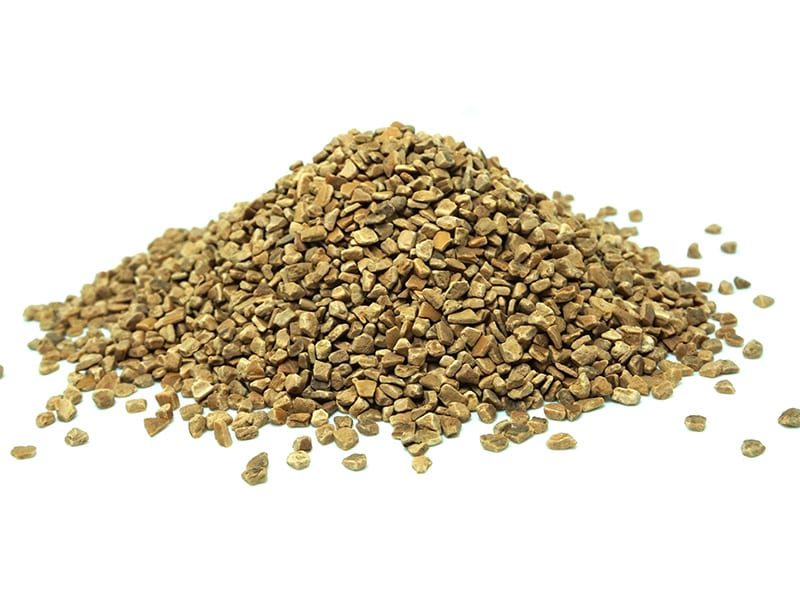
Founded in 1992, Xiamen Jin Tai Jin Grinding Technology Co.,Ltd. (SurfacePolish) engineers and manufactures 21 machine platforms backed by 24 granted Chinese IP rights and more than 200,000+ solutions across certified facilities (ISO 00726Q01571R001, CE M.2023.206.C88121, and CE M.2023.206.C88120). Alongside ZL circular bowls, ZXL/L1300–L1800 divided troughs, LLB50/LLF120 centrifugal finishers, OBD-30..100 magnetic polishers, and heated 35/35A/70/70A centrifugal dryers, we supply LC10, MC8, JTS5, HM3, JTJ20, JTJ25, JTJ50, and JTJ60 compounds matched to fast-cut and fine-cut high-frequency ceramic, resin plastic cones, iron-free high-alumina spheres, 304 stainless balls and magnetic pins, corncob, and walnut shell (8#-80#). Standard machines ship in 25–35 days and custom lines ship in 45–60 days. Send sample raw DMLS or SLM metal parts to surface-polish.com for complimentary two-stage process validation. Honest boundaries apply: we do not supply DMLS metal printers, vacuum stress-relief furnaces, or electropolishing baths.
Frequently Asked Questions About Additive Manufacturing Surface Finish
Why do 3D-printed metal parts need longer Stage 1 cutting than CNC parts?
DMLS and SLM parts carry partially sintered satellite powder spheres and layer stair-steps that are much rougher than billet CNC toolpaths. Stage 1 high-frequency ceramic (or plastic cones on AlSi10Mg) must level those peaks flat before Stage 2 burnishing can shine.
Can high-frequency ceramic media smooth AlSi10Mg 3D-printed aluminum?
Heavy vitrified ceramic stones peen and dimple soft AlSi10Mg printed aluminum. Level printed aluminum with lightweight resin plastic cones (compound-LC10) and brighten with iron-free high-alumina spheres (HM3 or JTJ50).
Can 304 stainless balls burnish 3D-printed Ti-6Al-4V titanium?
No—heavy 304 steel balls risk free-iron transfer onto passive titanium surfaces. Burnish printed titanium strictly with iron-free high-alumina spheres and compound-HM3 or JTJ50.
How do I prevent ceramic chips from lodging inside printed lattice structures?
Select media shapes and dimensions via non-lodging media sizing rules relative to your smallest lattice window or cooling channel, and screen out worn slivers weekly.
Why did my 3D-printed parts turn dark grey inside the vibratory bowl?
Dark grey smut indicates un-blown loose build powder, dirty closed-sump recirculation, or CNC post-machining oil carry-over. Depowder parts first, pre-degrease CNC-machined faces, and run single-pass flow through with LC10.
Are LLB50 centrifugal disc finishers faster than ZL bowls on DMLS parts?
Yes—for small-to-medium dense printed parts, LLB50 and LLF120 centrifugal machines multiply shear energy cleanly, cutting long Stage 1 roughness-leveling cycle times substantially.
What drying setup stops rust and water spots inside porous printed parts?
Rinse exiting parts beneath a softened/RO spray bar on the separator screen, spin-dry immediately in a heated 35, 35A, 70, or 70A dryer, and add warm dry corncob wipe buffing when needed.
How can I test two-stage mass finishing on my 3D-printed parts before ordering?
Send representative raw DMLS or SLM parts (after support removal and depowdering) to surface-polish.com for complimentary lab testing; our engineers validate Stage 1 leveling, Stage 2 burnishing, and 35A/70A drying and return finished samples before you order.
 +86-592-2381506


 IPv6 network supported