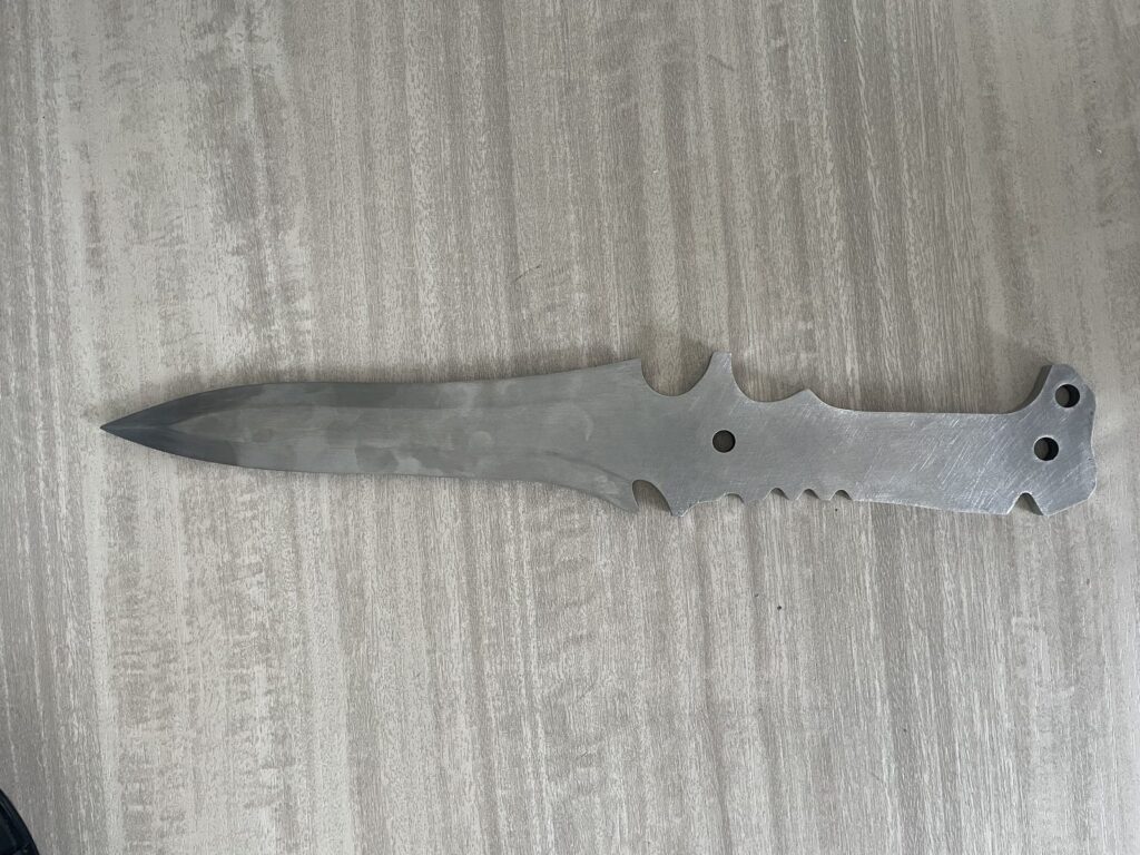
Brushed vs Satin vs Mirror Finish: How to Specify and Produce Each One
The words brushed, satin, and mirror get used loosely in design offices, machine shops, and purchasing departments. In practice, the difference between these metal finishes is not merely cosmetic. It dictates how an alloy resists atmospheric corrosion, how easily a surface can be sanitized in a hygienic facility, what kind of maintenance schedule it demands in service, and—critically—what manufacturing operations are required to produce it repeatedly at scale. When engineering drawings specify a surface finish with vague commercial labels rather than defined production parameters, parts from different suppliers or even separate production batches rarely match. This guide breaks down what actually separates brushed, satin, and mirror finishes, how to eliminate ambiguity on your engineering drawings, and how each grade is produced in batch manufacturing. If you are already dealing with parts that came out cloudy, hazy, or discolored and need to troubleshoot the root cause of an unexpected surface defect, start with our process guide on polishing stainless steel. If your primary challenge is selecting the right chemical carriers or liquid brightening agents for stainless grades, consult our review of stainless steel polish. For an analysis of solid bar waxes versus water-soluble pastes, refer to our comparison of stainless steel buffing compounds. This article focuses strictly on defining the three finishes, establishing enforceable drawing specifications, and designing multi-stage production routes that hit your target grade on the factory floor.
1. What Each Finish Name Actually Means (and What It Doesn't)
In workshop terminology, brushed, satin, and mirror describe three distinct optical and tactile surface conditions. Each finish reflects light differently because each represents a distinct micro-topography created by specific mechanical cutting or burnishing mechanisms.
```
─-------------------------------------------------------------------------─ │ SURFACE PROFILE COMPARISON SCHEMATIC │ ─-------------------------------------------------------------------------─ │ 1. BRUSHED (ASTM No. 4) │ │ Parallel, directional grooves created by bounded linear abrasives │ │ /\_/\_/\_/\_/\_/\_/\_/\_/\_/\_/\_/\_/\_/\_/\_/\_/\_/\_/\_/\_/\_/\ │ │ [Unidirectional Lay │ High Tactile Texture │ Diffuse Specular Line] │ ─-------------------------------------------------------------------------─ │ 2. SATIN │ │ Randomized, micro-peened or multi-directional blended micro-depressions│ │ ~^~.~^~.~^~.~^~.~^~.~^~.~^~.~^~.~^~.~^~.~^~.~^~.~^~.~^~.~^~.~^~. │ │ [Non-Directional Lay │ Smooth Matte Texture │ Soft Multi-Angle Glow]│ ─-------------------------------------------------------------------------─ │ 3. MIRROR (ASTM No. 8) │ │ Planarized micro-peaks; surface rolled flat via plastic deformation │ │ _________________________________________________________________ │ │ [Zero Discernible Lay │ Glass-Smooth │ True Specular Reflection] │ ─-------------------------------------------------------------------------─
```
Brushed (ASTM No. 4) — Directional Grain You Can See and Feel
A brushed finish—historically referenced in architectural and mill standards as an ASTM No. 4 finish—is characterized by fine, parallel abrasive lines running uniformly along a single axis. When you inspect a brushed stainless part under a direct light source, you see a sharp, elongated linear reflection oriented perpendicular to the grit lines. Run a fingernail across the grain, and you will feel noticeable mechanical resistance; run it parallel to the grain, and the surface feels smooth. A brushed finish is produced by mechanically tracking fixed abrasive grains across the metal under continuous linear contact, leveling surface peaks while leaving behind parallel micro-troughs.
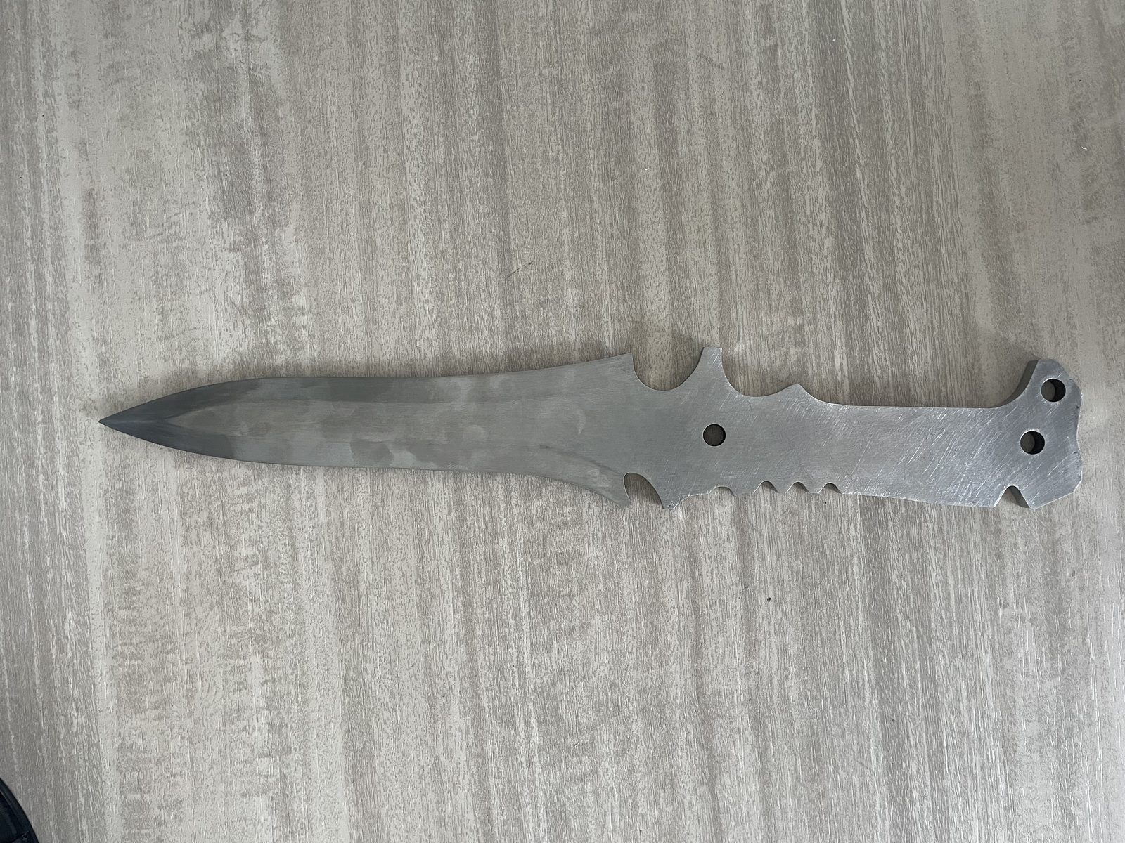
Satin — Non-Directional, Low-Glare, the Grade in Between
A satin finish is frequently confused with a brushed finish, but its micro-geometry is fundamentally different. While a brushed surface exhibits a definite unidirectional "grain" (or lay), a true satin finish is non-directional, silky to the touch, and features a soft, diffuse luster that scatters incident light evenly across all angles. Under magnification, a quality satin finish does not display continuous parallel micro-trenches. Instead, it consists of microscopic, overlapping, multi-directional scratches or tiny indented dimples. Because it lacks a dominant grain orientation, satin finishes reflect light with a gentle, matte sheen rather than sharp specular highlights. It provides the visual softness of a fine surface without the directional glare of brushed sheet or the high-maintenance reflectivity of a mirror.
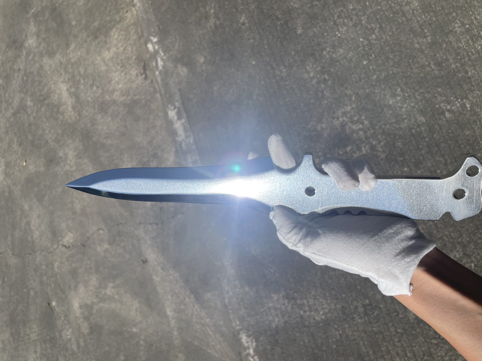
Mirror (ASTM No. 8) — True Reflection and Zero Visible Texture
A true mirror finish—often specified as an ASTM No. 8 finish—is the pinnacle of mechanical surface refinement. In this condition, the metal surface has been leveled, smoothed, and burnished until all visible scratch patterns, directional grinding marks, and micro-voids are eliminated. A mirror surface does not merely look bright; it produces an undistorted, crisp specular reflection. If you place a printed document perpendicular to an ASTM No. 8 surface, you should be able to read the reflected text without optical distortion or hazing. To the touch, it feels completely frictionless, behaving like polished plate glass. Achieving this requires removing coarse machining peaks and progressively burnishing the metal's outer layer flat through multi-stage mechanical operations.
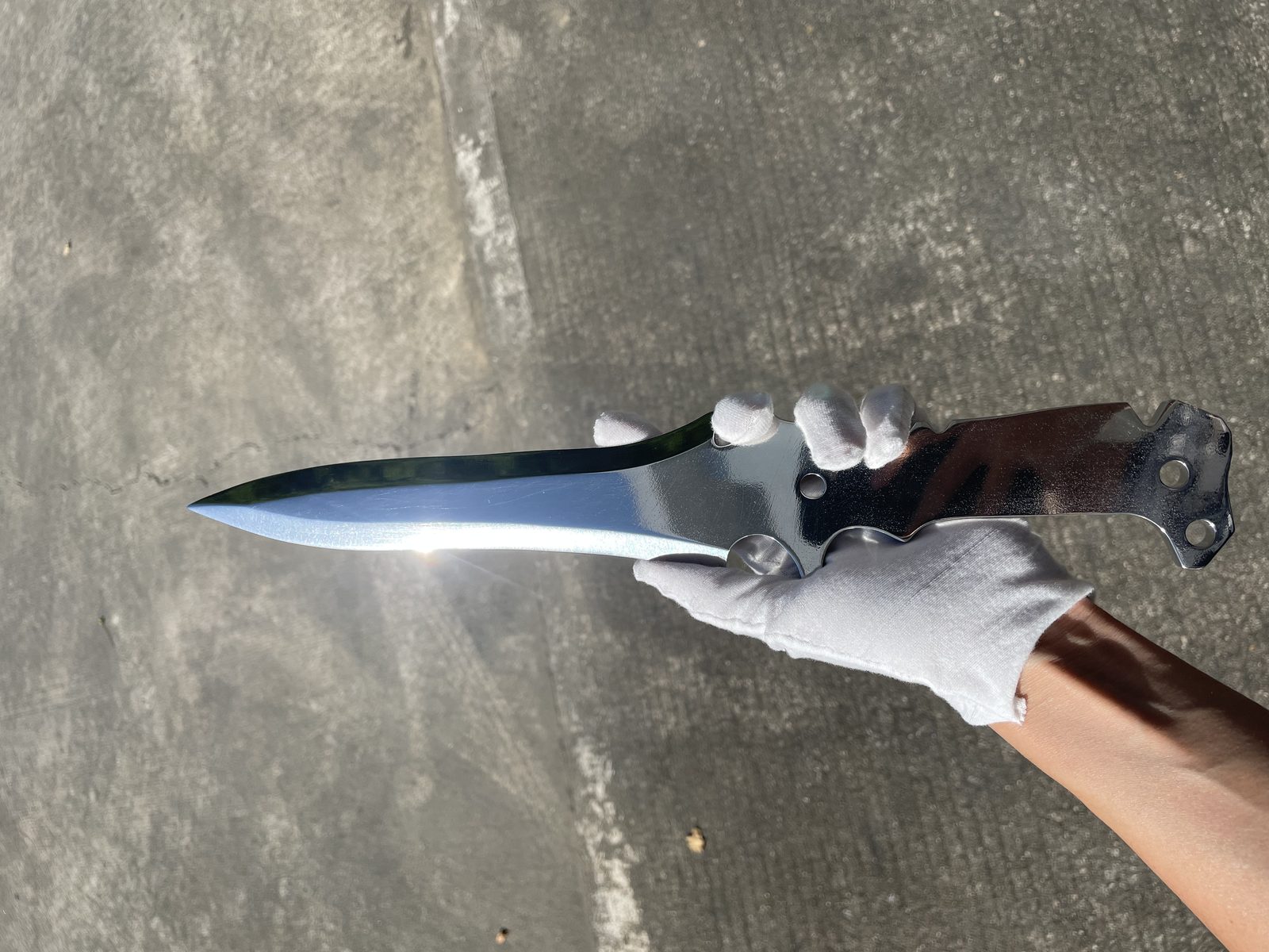
Why the Name Alone Is Not a Specification
Calling out "brushed finish" or "mirror finish" in the notes block of a manufacturing print invites wide variation. These commercial terms describe a general visual impression, not an enforceable physical threshold. To one supplier, a "brushed finish" means passing an enclosure against a coarse 80-grit flap wheel on a hand grinder. To another, it means passing sheet metal through an automated, coolant-fed wide-belt line equipped with a 240-grit aluminum oxide belt followed by an oscillating non-woven web brush. Both suppliers delivered a surface that can be called "brushed," yet the two parts will look completely mismatched when assembled side by side on a finished assembly.
| Evaluation Metric | Brushed Finish (ASTM No. 4) | Satin Finish | Mirror Finish (ASTM No. 8) |
|---|---|---|---|
| Primary Visual Trait | Clear, parallel, unidirectional linear grain lines | Soft, low-glare diffuse sheen; non-directional | True, undistorted specular reflection; zero grain |
| Tactile Characteristic | Distinct directional drag across the grain | Smooth, silky, low-friction feel in all directions | Completely smooth; glass-like contact feel |
| Dominant Surface Lay | Strictly unidirectional (parallel to tool motion) | Non-directional, randomized, or isotropic | Non-directional; no discernible lay |
| Scratch Hiding Ability | Excellent (parallel scratches blend into grain) | Moderate (hides minor handling scuffs well) | Extremely poor (every hairline scratch shows) |
| Fingerprint Sensitivity | Moderate (oil collects in grain lines) | Low (diffuse texture resists visible smudging) | High (surface oils cause immediate visual hazing) |
| Primary Batch Production Route | Wide-belt sander or fixtured linear stroke linisher | Vibratory mass finishing with fine plastic/ceramic media | Multi-stage centrifugal barrel or vibratory ball burnish |
2. The Specification Trap: Same Name, Different Surface
The single most common procurement failure in metal finishing occurs when a design engineer writes Finish: Satin Stainless on a production drawing, signs off on a hand-polished golden sample from a domestic prototyping shop, and then awards a production run of several thousand pieces to an overseas production plant. When the production batch arrives, the parts look hazy, dull, or overly reflective compared to the sample. The vendor has not necessarily cheated on the process; the drawing simply failed to specify the surface unambiguously.
```
─-------------------------------------------------------------------------------─ │ THE 4-FIELD UNAMBIGUOUS SURFACE FINISH CALLOUT │ ─-------------------------------------------------------------------------------─ │ │ │ FIELD 1: STANDARD CLASSIFICATION │ │ [ASTM A480 No. 4 / EN 10088-2 2J / DIN 17440] │ │ + │ │ FIELD 2: RETAINED PHYSICAL COUPON │ │ [Reference: Master Finish Sample QA-SS-04, Rev B] │ │ + │ │ FIELD 3: MEASURED ROUGHNESS WINDOW │ │ [Both Upper and Lower Roughness Thresholds Verified via Stylus Tracing] │ │ + │ │ FIELD 4: DIRECTIONAL LAY DESIGNATION │ │ [Unidirectional Parallel to Datum A / Non-Directional Multi-Axis (M)] │ │ │ ─-------------------------------------------------------------------------------─ │ RESULT: Zero Discrepancy Across Dispersed Manufacturing Sites and Subcontractors│ ─-------------------------------------------------------------------------------─
```
Where the Ambiguity Comes From — The Abrasive Sequence, Not the Label
Surface classification standards (such as ASTM A480 or EN 10088-2) describe the appearance and typical production methods of stainless finishes, but they do not lock down a universal recipe. An ASTM No. 4 specification permits finishing with abrasives ranging broadly from 120-grit up to 320-grit. A manufacturer finishing 304-grade stainless with fresh, sharp 120-grit silicon carbide belts will generate deep, aggressive micro-troughs with sharp valley peaks. Another supplier running 240-grit aluminum oxide belts that have already processed hundreds of parts will produce shallow, rounded troughs with a noticeably higher luster. Both processes technically comply with a generic "ASTM No. 4" label, yet their functional behavior and optical appearance are completely different.
The Four Fields That Make a Finish Spec Unambiguous
To create a production drawing that two independent suppliers can interpret identically, an engineering specification must contain four discrete fields:
- The Standard Designation: Reference an industry standard baseline, such as ASTM A480 (No. 4, No. 6, No. 7, or No. 8) or ISO 1302 finish designations.
- A Retained Physical Sample Reference: Call out a specific physical master sample held in quality control: e.g., "Finish must visually match Retained Master Coupon Ref #SS-FIN-04, Rev C."
- An Agreed Measured Roughness Window: Define both an upper limit and a lower threshold for surface roughness verified across quality control stylus traces. Specifying only a maximum roughness is a dangerous mistake: a part that is polished completely smooth will pass an upper roughness limit, yet look entirely wrong next to a satin component. Specify an acceptable band that reflects functional requirements.
- The Direction of Lay: Specify the directional orientation of the texture relative to a drawing datum: e.g., "Lay parallel to long axis of Datum A" for brushed parts, or "Non-directional / multidirectional (M)" for satin and mirror surfaces.
What Happens When You Skip the Sample
Instrumentation alone cannot fully describe an aesthetic surface. A surface roughness gage measures vertical profile deviations along a 2D line. It does not measure reflectivity, scattering angle, or ambient color tone. It is entirely possible to machine two stainless coupons that register identical average roughness profile readings, yet one appears bright silver-white while the other looks dark, cloudy, and burnished. This happens because the shape of the peaks and valleys (the peak count and valley width) alters light refraction even when the average peak-to-valley height is numerically comparable. Without a physical, retained boundary coupon signed off by both the design team and the manufacturing plant, evaluating visual compliance on the factory receiving dock becomes an unwinnable debate over personal perception.
Reading a Supplier's Finish Claim for What It Actually Says
When reviewing an external supplier's quotation, read their finishing claims with mechanical scrutiny. If a quote states "standard commercial polish," that is an open admission that they will use whatever grinding wheels, abrasive media, or hand pads happen to be mounted on their finishing stations that week. If they quote "mirror polish" without specifying the pre-grinding stages, compound formulations, or an automated vibratory finishing machine routing, they are likely relying on an operator with an open-face buffing lathe. That manual route may deliver a reflective look on the broad flats of a prototype, but it will round over critical edges, dish out clearance holes, and drift across production runs.
3. Choosing Between Them: The Engineering Decision
Selecting among brushed, satin, and mirror surfaces is rarely a purely aesthetic decision. Each grade carries functional advantages and distinct mechanical vulnerabilities in service.
```
─-------------------------------------------------------------------------─ │ ENGINEERING FINISH SELECTION MATRIX │ ─-------------------------------------------------------------------------─ │ │ │ HYGIENIC & SANITARY │ │ [Pharmaceutical, Dairy, Cleanrooms, Bio-Processing] │ │ --\> SPECIFY: MIRROR (ASTM No. 8) or ELECTROPOLISHED │ │ --\> WHY: Flat profile removes micro-crevices; prevents biofilm build-up│ │ │ │ HIGH CONTAMINANT & MARINE EXPOSURE │ │ [Coastal Installations, Offshore Enclosures, Chemical Washdown] │ │ --\> SPECIFY: SATIN or SPECULAR POLISHED (AVOID UNIPOLAR BRUSHED) │ │ --\> WHY: Directional brush valleys trap salt; non-directional sheds it │ │ │ │ FREQUENT OPERATOR HANDLING & ARCHITECTURAL │ │ [Elevator Panels, Machine Guards, Enclosures, Consumer Touchpoints] │ │ --\> SPECIFY: BRUSHED (ASTM No. 4) or NON-DIRECTIONAL SATIN │ │ --\> WHY: Directional grain masks daily wear, abrasion, and fingerprints│ │ │ ─-------------------------------------------------------------------------─
```
Cleanability and Hygiene — When Mirror Is the Only Acceptable Answer
In semiconductor handling, dairy processing, biopharmaceutical reactors, and medical device manufacturing, microscopic surface crevices represent contamination hazards. The parallel micro-grooves of a brushed finish create sheltered micro-valleys where chemical residues, bacteria, and particulate can lodge, resisting standard clean-in-place (CIP) spray washing. A mirror finish, by flattening microscopic surface asperities and rolling down high micro-peaks, minimizes mechanical adhesion points. Fluids sheet off cleanly, biological materials find no anchor points, and wiping protocols require minimal friction. When hygiene, non-shedding, and absolute cleanability are functional requirements, mirror finishing is the necessary engineering choice.
Corrosion Behaviour — Why Brushed Traps What Mirror Sheds
Stainless steel relies on an ultra-thin, continuous chromium oxide (Cr_2O_3) passive layer to resist oxidation. While all clean stainless alloys will form this film in the presence of atmospheric oxygen, the physical topography of the surface strongly influences how that film survives in aggressive working environments. A coarse brushed surface installed in an outdoor marine or industrial chemical environment is significantly more susceptible to tea-staining and localized pitting than an equivalent mirror or fine satin surface. Salt crystals, airborne chlorides, and industrial chemical aerosols settle into the parallel valleys of a brushed grain. Rainwater or humidity deposits into these micro-crevices, creating stagnant, oxygen-depleted micro-cells beneath the salt deposits. This localized chloride concentration attacks the passive film, initiating micro-pitting corrosion. A specular mirror surface, lacking these microscopic valleys, sheds airborne moisture and washdown fluids rapidly, keeping the passive film evenly exposed to ambient oxygen.
Glare and Scratch Hiding — Where Brushed Wins in Service
Where brushed stainless steel loses ground in hygienic performance, it excels in rugged, high-contact operating environments. A pristine mirror-finished panel is an unforgiving surface. A single contact with an operator's ring, a dropped hand tool, or an abrasive wipe with a shop rag will leave an immediate, highly visible hairline scratch. Furthermore, high specular reflectivity causes intense visual glare under industrial LED overhead lighting or direct sunlight, causing operator eye fatigue on control consoles and machine guards. A brushed surface (ASTM No. 4) diffuses harsh ambient light into a soft linear highlight. More importantly, because the metal is already pre-conditioned with thousands of fine, parallel micro-scratches, light everyday abrasions that run parallel to the grain blend into the pattern invisibly. For industrial equipment housings, elevator cabs, and food service prep tables that see continuous daily wear, brushed stainless preserves its perceived quality far longer than mirror-finished sheet.
Repair — Which Grade Can Be Reworked After Damage
Before finalizing a surface callout on an engineering print, consider how the component will be repaired when it gets scratched during downstream assembly, shipping, or field operation:
- Brushed Finishes: Straightforward to rework in the field. Using non-woven abrasive hand pads or portable linear drum sanders matched to the original grit specification, an experienced technician can stroke parallel to the original grain, blending a local handling scratch into the surrounding field without leaving obvious witness marks.
- Satin Finishes: Moderately difficult to spot-repair. Blending a localized repair into a non-directional, isotropic satin field requires careful feathering with orbital finishing tools or localized micro-blasting. Any excessive localized pressure creates a shiny or discolored halo.
- Mirror Finishes: Extremely difficult to repair on site. You cannot spot-repair an ASTM No. 8 surface with hand tools. Polishing an isolated scratch with a hand-held buffing wheel removes metal locally, dishing out the reflection and leaving an optical distortion known as an "orange peel" or lens effect. Restoring an authentic mirror surface typically requires stripping the component, leveling the entire panel back down through coarse abrasives, and progressing completely through the cutting and color-buffing stages on stationary machinery.
4. How Each Grade Is Produced at Scale
One of the sharpest disconnects between design engineering and manufacturing execution lies in understanding how surface grades are produced in volume. A prototype maker can polish almost any geometry using hand files, sandpaper sheets, and an open buffing arbor. In continuous mass production, finishing methods fall into distinct mechanical routes.
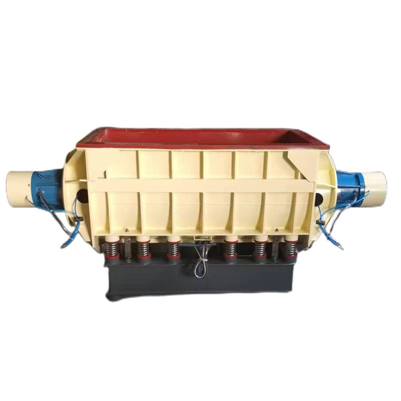
Industrial rectangular tub vibrators allow discrete batch parts to be processed in continuous rolling media beds, providing uniform satin and pre-plate finishes.
Route A — Abrasive Belt and Non-Woven Wheel (Flat Panels, Low Volume)
An honest engineering boundary: Automated wide-belt grinding machines, flat-bed stroke linishers, and planetary tube sanders are specialized machine tool classes used for sheet goods, flat plates, and simple structural tubes. We do not manufacture wide-belt sheet grinding systems. However, any objective review of metal finishing must acknowledge that for continuous flat sheets, architectural plates, and long extrusions, wide-belt lines are the standard industrial route for creating directional ASTM No. 4 brushed finishes. These machines feed flat workpieces beneath spring-loaded tension heads carrying wide coated-abrasive belts lubricated by mineral oils or water-soluble emulsions, followed by oscillating non-woven Scotch-Brite-style flap rolls to de-burr and unify the grain. When parts are small, stamped, cast, or exhibit complex three-dimensional contours with pockets, ribs, and internal bosses, wide-belt grinding cannot reach the surfaces, and mechanical mass finishing takes over.
Route B — Vibratory Mass Finishing (Batch Parts, Satin and Brushed)
For high-volume production of three-dimensional parts—such as machined fittings, stamped hinges, manifold housings, and medical brackets—vibratory finishing machines provide an efficient route to consistent satin and pre-polish surfaces. In an industrial vibratory bowl or tub vibrator, hundreds of workpieces are submerged in a dynamic bed of pre-formed abrasive media charged with a continuous flow of water and chemical compound. The eccentric drive of the vibratory machine causes the entire load to circulate in an orderly, helical rolling motion. Because the media surrounds the workpieces from all directions, it abrades every exterior edge, face, and pocket simultaneously. By selecting dense plastic-bonded media impregnated with fine silicon carbide or aluminum oxide abrasives, vibratory finishing creates an exceptionally uniform, non-directional satin finish across large batches, completely eliminating manual handling lines and part-to-part variation.
Route C — Centrifugal Barrel and Ball Burnishing (Mirror on Small Parts)
Achieving a specular mirror luster on large volumes of small-to-medium parts without manual buffing requires intense mechanical energy. This is the domain of centrifugal barrel finishing machines and high-energy vibratory burnishers.
```
─-------------------------------------------------------------------------─ │ CENTRIFUGAL BARREL PROCESS: PLANETARY ROTATION DYNAMICS │ ─-------------------------------------------------------------------------─ │ │ │ [Main Turret Rotation: Counter-Clockwise] │ │ \<--- │ │ │ │ +-------------------+ +-------------------+ │ │ │ BARREL #1 │ │ BARREL #2 │ │ │ │ (Rotates CW │ │ (Rotates CW │ │ │ │ High G-Force) │ │ High G-Force) │ │ │ │ [Media + Parts] │ │ [Media + Parts] │ │ │ +-------------------+ +-------------------+ │ │ │ │ O [Central Hub] │ │ │ │ +-------------------+ +-------------------+ │ │ │ BARREL #4 │ │ BARREL #3 │ │ │ │ (Rotates CW │ │ (Rotates CW │ │ │ │ High G-Force) │ │ High G-Force) │ │ │ │ [Media + Parts] │ │ [Media + Parts] │ │ │ +-------------------+ +-------------------+ │ │ │ │ ---\> │ ─-------------------------------------------------------------------------─ │ ACTION: Up to 10-20G forces slide media against parts with zero part- │ │ on-part impingement, producing true isotropic mirror finishes. │ ─-------------------------------------------------------------------------─
```
A centrifugal barrel machine mounts multiple sealed processing drums to the perimeter of a large central turret. As the turret spins rapidly in one direction, the individual drums counter-rotate on their own axes. This dual-rotation planetary kinematics subjects the media bed to gravitational forces up to 10 to 20 times normal gravity. Inside the barrels, parts and non-abrasive, high-density steel finishing media or micro-crystalline porcelain balls slide against one another under heavy compaction pressure. Instead of cutting metal away, this high-energy sliding action plastically deforms microscopic surface peaks, flowing the surface flat at the molecular level. The result is a true, isotropic mirror finish delivered across hundreds of loose hardware components per batch, with sharp crisp edges preserved and zero parting-line distortion.
Matching Media Shape and Size to the Target Grade
You cannot produce a refined satin or mirror finish using general-purpose rough-cut stones. Media geometry directly governs surface profile and edge contour:
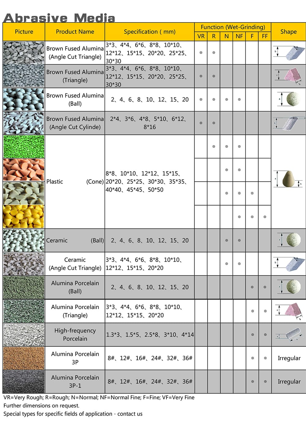
Selecting the correct media profile—from aggressive ceramic cutting cylinders to fine resin cones—governs how abrasives interface with workpiece contours.
- Angular Shapes (Triangles, Stars): Sharp corners track aggressively into internal fillets and weld toes. They are ideal for initial cutting stages, but their edges can leave tiny peening witness marks on soft stainless faces if run during final stages.
- Radiused Shapes (Cones, Paraboloids, Spheres): Rounded media shapes slide smoothly over flat faces and roll across machined contours without digging in. For non-directional satin finishing, resin-bonded plastic cones with a fine abrasive mix deliver a silky, matte texture with zero visual tracking lines.
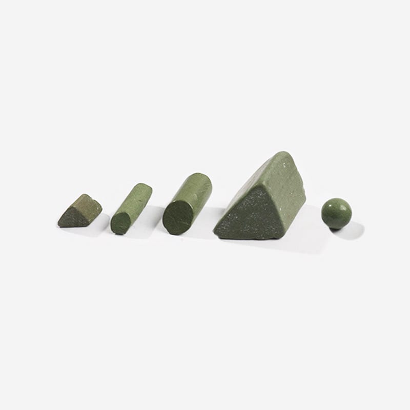
- Non-Abrasive High-Density Porcelain and Steel Balls: Used exclusively for mirror burnishing. Because these media contain zero abrasive grain, they remove no metal stock. Instead, their high mass and smooth outer surface burnish microscopic peaks flat under high fluid lubrication.
Ceramic tumbling media geometries: high-density triangles, cylinders, and spheres engineered for specific material cutting and burnishing operations.
To review comprehensive sizing tables and composition guidelines across ceramic, synthetic, and organic types, explore our tumbling media selection guide.
What the Compound Is Doing at Each Stage
Dosing plain tap water into a vibratory or centrifugal machine will not deliver a quality finish. Chemical finishing compounds are precision-formulated chemical agents that perform three distinct jobs:
- Lubrication and Boundary Layer Control: During fine cutting and satin processing, the compound controls the friction coefficient between abrasive grains and the stainless substrate. If lubrication is too thin, the media bites aggressively, tearing the metal and leaving coarse gouges; if it is too thick, the media hydroplanes, stalling material removal.
- Swarf Emulsification and Suspension: As grinding media abrades metal, microscopic stainless particles shed into the fluid bath. A high-quality compound encapsulates this fine swarf, keeping it suspended in solution so it flushes continuously out the drain ports rather than re-depositing into the surface pores.
- Chemical Brightening and Passivation: During final mirror ball-burnishing stages, slightly acidic or specially inhibited neutral compounds clean microscopic surface oxides, allowing hardened steel or porcelain balls to contact pure, bright metal. This chemical action brings out an authentic, deep specular luster while simultaneously building a corrosion-resistant passive film.
5. The Multi-Stage Sequence Nobody Documents
In experienced finishing operations, mirror and fine satin surfaces are never produced in a single processing step. Bypassing progressive steps is the primary reason machine shops waste hours of processing time only to yield cloudy, scratched components.
```
─-------------------------------------------------------------------------─ │ THE 3-STAGE PROGRESSIVE FINISHING ROUTE │ ─-------------------------------------------------------------------------─ │ │ │ RAW AS-MACHINED OR STAMPED PART │ │ [Heavy Milling Marks, Tool Burrs, Heat Scale, Coarse Scratches] │ │ │ │ │ v │ │ STAGE 1: CUTTING (STOCK LEVELING) │ │ Equipment: Vibratory Trough or Heavy-Duty Bowl │ │ Media: Medium-to-Fast Cut Ceramic Triangles / Angle-Cut Cylinders │ │ Compound: Acidic / Alkaline Cleaning & Detergent Formulation │ │ Goal: Level tool peaks completely; bring surface to uniform roughness │ │ │ │ │ v │ │ STAGE 2: BLENDING (PRE-POLISH UNIFICATION) │ │ Equipment: Vibratory Bowl or Centrifugal Disc Finisher │ │ Media: Fine-Grit Resin-Bonded Synthetic Plastic Cones │ │ Compound: Mild Lubricating Burnishing Formulation │ │ Goal: Erase Stage 1 micro-trenches; establish uniform satin lay │ │ │ │ │ v │ │ STAGE 3: SPECULAR BRIGHTENING (BURNISHING) │ │ Equipment: High-Energy Centrifugal Barrel or Vibratory Tub │ │ Media: Non-Abrasive Porcelain Spheres / Hardened Stainless Pins │ │ Compound: High-Luster Chelation and Surface Conditioning Surfactant │ │ Goal: Plastically deform micro-peaks; achieve mirror reflectivity │ │ │ ─-------------------------------------------------------------------------─
```
Why You Cannot Jump from As-Machined to Mirror
Machined, stamped, or laser-cut stainless surfaces feature microscopic profile peaks with steep valley depths. If an operator places an as-machined part directly into a mirror-finishing stage using fine porcelain spheres or an open cotton buffing mop, the smooth burnishing media cannot shear off those deep, steep peaks. Instead, the burnishing tool simply peens, rolls, and smears the tops of the metal peaks over the underlying micro-valleys. To the naked eye, the part may appear shiny under a quick glance, but examine it under a bright point light and you will see a network of cloudy, distorted scratches trapped beneath a smeared surface skin.
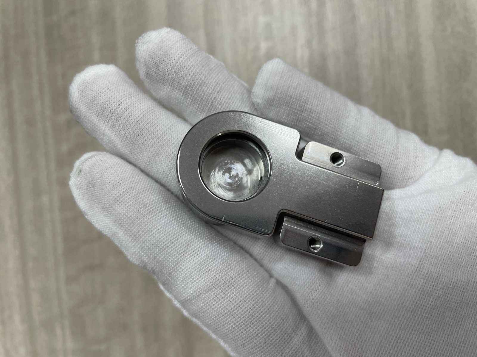
To achieve an authentic mirror finish, the metal must be leveled progressively so that the valley depths of the preceding abrasive stage are completely erased by the current stage.
Stage 1 — Cutting (Removing the Previous Operation's Marks)
The first stage has a single mechanical objective: complete stock leveling. It must abrade away rough CNC tool passes, EDM recast layers, laser dross, or deep handling scratches down to a uniform, controlled depth.
- Industrial Mass Route: Process parts in an open tub vibrator using medium-cut ceramic angle-cut triangles with a continuous rinse of an emulsifying compound.
- Manual / Batch Flat Route: Perform initial linear grain tracking using coarse-to-medium coated abrasive belts (typically 120-grit to 180-grit aluminum oxide).
- The Process Gate: Do not exit Stage 1 until all directional cutter tracks and localized scratches are gone. If deep tool gouges remain, running downstream polishing stages will only highlight them.
Stage 2 — Blending (Unifying the Surface)
Stage 2 transitions the part from a rough, raw-leveled state into a smooth, intermediate pre-polish.
- Industrial Mass Route: Transfer parts into a circular vibratory bowl loaded with high-density, resin-bonded plastic cones or fine synthetic pyramids. The lighter, softer plastic matrix cushions contact, rounding sharp valley profiles and eliminating the coarse grinding lines left by ceramic media.
- The Transition Point: Stage 2 is where an authentic Satin Finish is finalized. If a non-directional, silky, low-glare appearance is your drawing's target finish, the process stops here. Parts undergo ultrasonic degreasing, clean water rinsing, and warm-air centrifugal drying.
Stage 3 — Brightening (Raising Reflectivity Without Cutting Deeper)
If your engineering drawing specifies an authentic Mirror Finish (ASTM No. 8), parts that have successfully cleared Stage 2 move to a dedicated brightening station.
- Industrial Mass Route: Load parts into a high-energy centrifugal barrel machine packed with smooth, non-abrasive porcelain spheres or polished stainless steel shot. Dosed with a specialized acidic or neutral brightening compound, the machine generates intense sliding pressure that flows the microscopic asperities flat without cutting away metal stock.
- Manual / Open Arbor Route: The part moves to an open buffing lathe. First, it receives a cut-buff using a stiff spiral-sewn cotton or sisal wheel dressed with black emery or brown tripoli compound, followed immediately by a final color-buff using a loose-leaf flannel wheel charged with green chromium oxide compound.
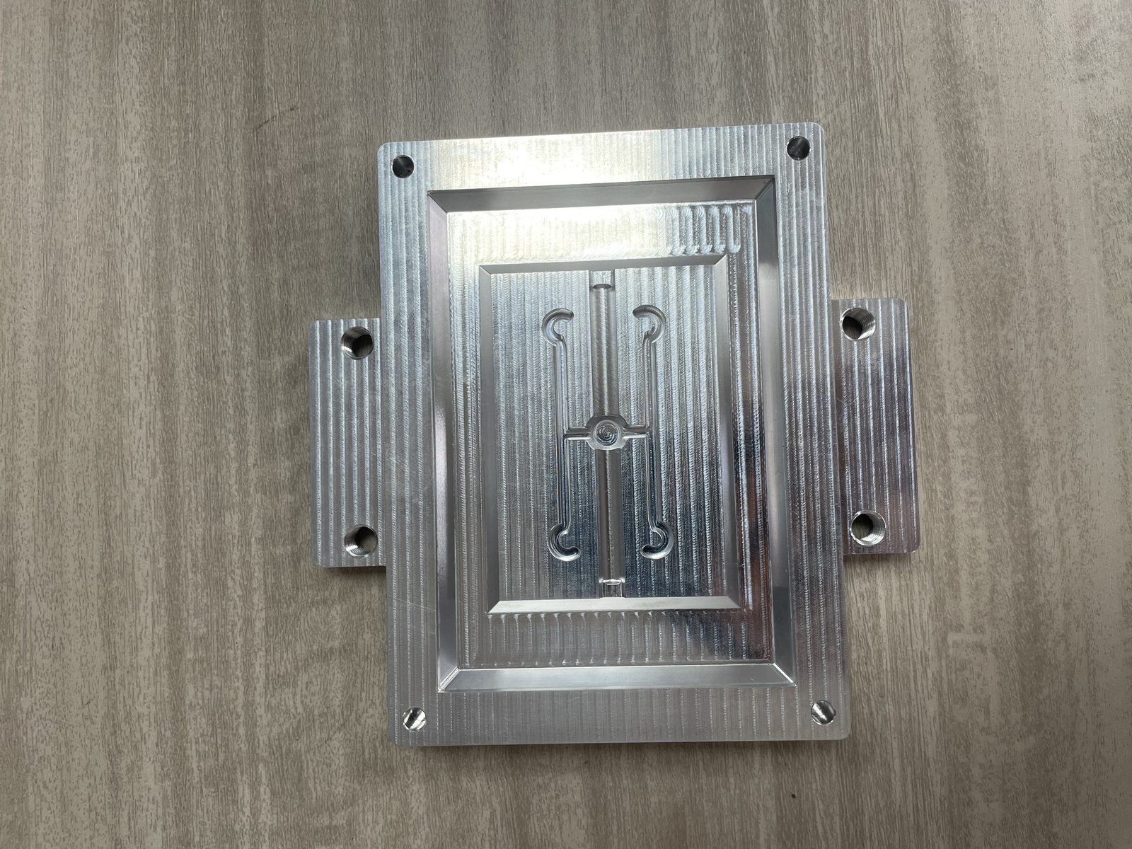
Multi-stage progressive refinement demonstrated on precision hardware: rough machined tool tracks transitioned to a refined pre-polish, followed by specular mirror burnishing.
When to Change the Media versus Change the Compound
When a process run fails to reach its target appearance, operators often waste time dumping expensive chemical compounds into the bath when the problem is mechanical, or swapping out tons of stone media when the problem is purely chemical:
- When you must change the media: If you look at the part under magnification and still see deep linear scratches, parallel tool marks, or micro-orange-peel dimples, your abrasive media is either too coarse, shaped incorrectly to reach into the part's radii, or you jumped to a fine stage too early. No chemical compound will erase an abrasive trench; you must step back to a more aggressive media grade.
- When you must change the compound: If the metal surface feels smooth and shows zero distinct scratches, but looks hazy, cloudy, yellowed, or discolored, your media is mechanically sound, but your chemistry has failed. You are dealing with metallic swarf re-deposition, incorrect solution pH, mineral precipitation from hard water, or an exhausted compound dosage. Flush the system and adjust chemical metering.
6. Mixed Finishes on One Part
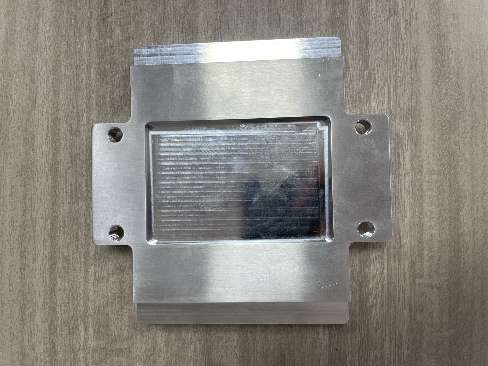
Some of the most demanding engineering components feature dual surface finishes on the same contiguous piece of metal: an architectural door handle with mirror-polished end bosses and a brushed grip shank; a luxury watch case with high-luster bevels flanking a fine-satin case side; or a surgical instrument with non-glare satin handles joined to glass-smooth, specular mirror working tips.
```
─-------------------------------------------------------------------------─ │ SELECTIVE MASKING & FIXTURING SCHEMATIC │ ─-------------------------------------------------------------------------─ │ │ │ STEP 1: BULK PROCESSING TO BASE FINISH │ │ Entire part processed through vibratory stages to complete SATIN base. │ │ [===================================================================] │ │ │ │ STEP 2: PRECISION ELASTOMERIC MASKING / FIXTURING │ │ Resilient EPDM / Silicone boots clamp over regions to remain Satin. │ │ +-------------------+ +-------------------+ │ │ │ MASKED ZONE: │ │ MASKED ZONE: │ │ │ │ Preserve Satin │ │ Preserve Satin │ │ │ +-------------------+ +-------------------+ │ │ │ │ │ │ v v │ │ STEP 3: SELECTIVE EXPOSURE TO HIGH-LUSTER OPERATION │ │ Unmasked working tip or center panel polished to mirror luster. │ │ [POLISHED MIRROR ZONE] │ │ │ ─-------------------------------------------------------------------------─ │ CRITICAL DEFECT TO PREVENT: Media bleed beneath the masking boundary │ │ leading to an irregular, wavy transition zone (blend line distortion). │ ─-------------------------------------------------------------------------─
```
Where Mixed Finishes Appear (Decorative Panel + Functional Edge)
Mixed finishes are chosen for practical operational reasons as well as industrial aesthetics. On aerospace control valves and pharmaceutical processing equipment, functional sealing surfaces, O-ring grooves, and valve seats are burnished to an ultra-smooth, low-drag finish to ensure a fluid-tight seal, while external structural flanges retain a non-directional satin finish to reduce part mass production costs and eliminate assembly glare. On hand-held tools, satin grip bodies prevent hand slippage under oily conditions, while working jaws are specularly polished to resist corrosion and chemical entrapment.
Masking and Fixturing for Selective Finishing
Producing mixed finishes on loose batch parts requires precise tooling design. You cannot simply apply thin adhesive vinyl tape to a part and drop it into an industrial vibratory trough; the relentless scrubbing action of heavy abrasive stones will peel tape edges within minutes, resulting in ragged, ruined boundary lines.
- Elastomeric Molded Masking Boots: High-volume components use custom-molded silicone or cast polyurethane masking boots. These resilient elastomer shells snap tightly over the areas that must be shielded from subsequent operations. The masking tool features molded sealing ribs that compress against the metal, establishing a tight mechanical barrier that prevents media stones and compound slurries from creeping onto finished faces.
- Rigid Spindle Fixturing: For parts processed in automated polishing cells or drag finishers, parts are mounted on rigid mechanical spindles. Custom clamping collars cover the protected zones while exposing only the target faces to high-energy media streams or buffing wheels.
Where Mixed Finishes Cause the Most Rework
The highest scrap rate on mixed-finish components occurs at the transition line (the blend boundary). If an operator performs hand-blending between a brushed field and a mirror flat, the buffing wheel inevitably wanders across the boundary, creating an uneven, wavy line of demarcation with rounded-over edges. On precision engineering components, transition lines should align with a sharp design break—such as a machined step, an undercut relief groove, or an internal corner radius. A natural step feature provides a physical landing point for masking fixtures, shielding the protected zone and producing crisp, repeatable demarcation boundaries without human error.
7. Failure Modes and What They Indicate
When a production run of finished components fails final quality control inspection, line supervisors often jump to conclusions, adjusting machine speeds or discarding functional media charges. Most mass finishing failures display clear physical symptoms pointing directly to a specific mechanical or chemical imbalance.
| Observed Surface Defect | Root Cause Mechanism | Shop-Floor Inspection Routine | Corrective Action Path |
|---|---|---|---|
| Patchy, uneven cloudy blotches; discolored halos across flats | Preceding coarse grinding marks were not leveled out; or media mix contains worn, undersized debris. | Inspect surface under low-angle oblique lighting; check for directional scratches running beneath the cloudiness. | Return load to Stage 1 leveling; screen out undersized worn media; verify minimum required run time per stage. |
| Surface fails to develop specular luster; remains dark gray | Chemical compound dosage is depleted; acidic imbalance; or incoming shop water is excessively hard. | Measure drain discharge pH; wipe wet parts with clean white cloth to check for dark re-deposited metal swarf. | Increase fresh compound metering; install water softening filtration; verify continuous drain port flushing. |
| Excessive edge rounding; dished-out clearance holes | Media density/mass is too high; cycle time is excessive; or parts are free-tumbling without protective fixturing. | Measure hole diameter and edge break profile using an optical comparator against the master part print. | Switch to smaller, lower-density media; shorten cycle duration; install compartmentalized dividers or fixtures. |
| Wavy, cross-hatched, or disoriented brush scratch lines | Loose linear tracking; parts rotated during belt pass; or manual feed velocity fluctuated over the head. | Visually trace individual scratch lines across the full part length against a straight edge. | Lock mechanical feed guides; maintain constant belt tension and steady conveyor speed; eliminate manual hand-guiding. |
| Orange peel / mottled specular distortion on mirror finish | Extreme localized friction heat during buffing; or excessive burnishing pressure over-peening the metal grain. | Examine the reflection under a grid pattern; look for wavy, lumpy distortion resembling the skin of an orange. | Lower contact pressure; reduce motor drive frequency; increase fluid cooling flow to prevent frictional surface flow. |
| Rapid tea-staining or flash rust within hours of unloading | Airborne carbon steel contamination; media previously used on carbon parts; or sluggish drying in ambient air. | Perform a standard ferroxyl test or 24-hr humidity exposure to identify free iron inclusions on the stainless surface. | Completely segregate stainless media from carbon steel lines; use dedicated acid passivation rinse; force-dry immediately. |
Diagnostic Breakdown: The "Why" Behind the Failures
Cloudy Blotches and Halos
When a satin or mirror part displays dull, cloudy islands surrounded by bright zones, the fault almost always lies in incomplete Stage 1 cutting. The operator saw the surface becoming uniformly bright and pulled the load too early. The microscopic high-peaks were burnished down, but the deeper valleys left behind by the primary milling machine or rough stamp press were never fully excised. The cloudy patch is light scattering off those recessed, unfinished micro-valleys.
Surface Fails to Brighten (Dark Smut Re-Deposition)
In wet vibratory and centrifugal processing, abraded stainless swarf is microscopic and reactive. If the compound flow rate is throttled back to "save chemicals," or if drainage screens become clogged with media chips, the bath turns into a dirty abrasive slurry. The tumbling stones hammer that suspended stainless grinding dust right back into the microscopic pores of the parts. Instead of a brilliant silver luster, the batch emerges with an unwashed, lead-gray cast.
Flash Rusting on Stainless Steel
Stainless steel should never rust under normal indoor ambient conditions. When freshly polished parts develop tiny reddish spots shortly after leaving the finishing cell, one of two contamination events occurred:
- Cross-Contamination: The finishing machine, wash tanks, or media stones were previously used to deburr standard carbon steel or ductile iron parts. Microscopic free iron particles embedded into the media's porous polyurethane lining were hammered into the stainless substrate, creating active galvanic rust cells. Always dedicate separate media charges and lining equipment exclusively to stainless steel processing.
- Slow Evaporative Drying: Leaving wet parts to air-dry slowly on a shop cart allows chloride-containing tap water to evaporate into concentrated chemical droplet cells, pitting the raw metal before its passive oxide film can naturally rebuild. Always run wet parts immediately through a clean deionized water rinse and dry them instantly using heated centrifugal spin dryers, continuous warm-air tunnel driers, or heated dry-cob absorption tumblers.
8. How to Verify You Received the Grade You Specified
Quality disputes between manufacturing plants and receiving inspection bays cost machine shops thousands of dollars in rejected purchase orders. To prevent subjective disagreements over visual finishes, establish an enforceable, documented verification protocol.
```
─-------------------------------------------------------------------------------─ │ RECEIVING INSPECTION FINISH VERIFICATION AUDIT │ ─-------------------------------------------------------------------------------─ │ │ │ 1. VISUAL AUDIT UNDER CONTROLLED LIGHTING │ │ Light Source: 1000–1500 Lux, 5000K Neutral White Diffuse Illumination │ │ Method: Hold production part side-by-side with Retained Master Coupon │ │ Angle of View: Compare at 30°, 60°, and 90° incidence angles │ │ │ │ │ v │ │ 2. SURFACE PROFILOMETER MEASUREMENT │ │ Instrument: Calibrated Stylus-Type Contact Profilometer │ │ Cutoff Length (λc): Set per ISO 4288 based on expected roughness │ │ Traces: Take 3 distinct traces (Parallel, Perpendicular, 45° to edge) │ │ Gate: Profile parameters must fall WITHIN the drawing's min/max window │ │ │ │ │ v │ │ 3. DOCUMENTATION AUDIT TRAIL │ │ Inspection Sign-Off Record must log: │ │ Production Batch / Heat Number │ │ Retained Master Coupon Serial Reference │ │ Stylus Profilometer Calibration Date and Cutoff Setting │ │ Inspector Signature, Date, and Final Disposition (Accept/Reject) │ │ │ ─-------------------------------------------------------------------------------─
```
Visual Comparison Against the Retained Sample
Visual inspection should never be performed haphazardly under flickering shop-floor fluorescent lights or direct outdoor sunlight. Inspect parts inside an inspection booth equipped with standard 5000K (neutral daylight) illumination providing 1000 to 1500 lux of diffuse light. Hold the production component directly adjacent to the serialized Retained Master Finish Coupon. Rotate the two parts together through 30-degree, 60-degree, and 90-degree angles of incidence relative to the light source:
- For Brushed Surfaces: Check that the grain lines run strictly parallel to the specified datum without wavering or drifting off-axis. Inspect the end-boundaries to ensure the grain does not wash out near edge chamfers.
- For Satin Surfaces: Verify that the surface exhibits an even, uniform diffuse sheen with zero directional grain tracking lines, zebra stripes, or shiny localized burnish marks.
- For Mirror Surfaces: Check the clarity of an inspection grid target reflected in the surface. Look for optical distortion, cloudiness, or recurring circular swirl marks left by unbalanced buffing wheels.
Measured Roughness — What to Ask Your Supplier For
When auditing a vendor's quality dossier, do not accept a certificate of conformance that simply states "Surface Finish: OK." Demand the primary inspection trace data:
- Cutoff Filter Length (λc (cutoff wavelength)): A surface roughness reading without an identified evaluation length and cutoff filter setting is technically meaningless. A reading taken with a 0.8 mm cutoff will yield a different mathematical output than one taken with a 2.5 mm cutoff over the same physical surface. Ensure their quality control lab adheres to ISO 4288 standards for filter selection.
- Multi-Axis Measurement Traces: On brushed finishes, a single trace running parallel down the bottom of an abrasive trough will register an artificially smooth reading. The inspection record must show stylus traces taken perpendicular to the grain orientation, where the instrument measures true peak-to-valley heights across the abrasive cuts. On satin and isotropic surfaces, traces should be recorded across multiple axes to confirm consistent non-directional lay.
The Inspection Record That Prevents Disputes
To prevent recurring quality disputes across supply tiers, establish an unambiguous finish inspection sign-off record that documents:
- The drawing number, revision level, and purchase order tracking code.
- The specific ID of the physical retained boundary coupon used for the visual audit.
- The calibrated serial number and stylus tip radius of the profilometer used for verification.
- The verified upper and lower measured roughness values across three distinct surface locations.
- A mandatory check confirmation verifying that cleaning and passivation protocols were completed prior to packaging.
By capturing these objective records, you transform finish quality control from an emotional visual argument into a repeatable, defensible engineering baseline.
9. Frequently Asked Questions (FAQ)
1. Is satin the same as brushed?
No. While people often use the terms interchangeably in conversation, they describe two distinct surface profiles. A brushed finish has an intentional, visible, unidirectional grain (or lay) created by linear abrasives tracking across the metal in parallel lines. A satin finish is non-directional or multi-directional, providing a smooth, low-glare, matte luster without parallel grain patterns.
2. Can a brushed finish be converted to mirror without re-machining?
Yes, provided the part has adequate wall thickness to accommodate the necessary material removal. However, you cannot jump straight from a brushed surface to a mirror buff. The parallel linear micro-grooves of the brushed surface must first be cross-cut and completely leveled using intermediate grinding stages (such as fine-grit plastic tumbling or orbital linishing) to erase the valley depths before mirror burnishing media can bring out an authentic specular reflection.
3. Which finish should I specify for a part that gets handled daily?
For high-traffic parts that experience regular manual contact, tool handling, or routine sliding wear, a Brushed (ASTM No. 4) or a fine Non-Directional Satin Finish is the best engineering choice. Minor surface scratches and abrasions sustained during daily service naturally blend into the existing micro-textured field, whereas a mirror finish will reveal every hairline scratch and fingerprint smudge immediately.
4. Does a mirror finish cost more to produce than brushed?
Yes. Producing an authentic mirror finish (ASTM No. 8) requires more sequential manufacturing stages, tighter progressive media steps, specialized high-density burnishing equipment or skilled manual lathe buffing, and meticulous clean-down between stages to prevent cross-grit contamination. Consequently, the manufacturing and inspection cost per piece for an authentic mirror finish is significantly higher than that of an intermediate brushed or satin part.
5. Can I get a consistent finish across parts from different batches?
Yes, but only if your engineering drawing replaces generic labels with an enforceable four-field specification: an industry standard classification, a reference to a physical retained master coupon, an agreed measured roughness acceptance window, and a declared lay direction. In mass production, processing parts in automated vibratory or centrifugal finishing systems delivers vastly superior batch-to-batch consistency compared to relying on manual hand-held grinding operators.
6. What do I do if my supplier's "No. 4" doesn't match my previous supplier's?
ASTM A480 permits a broad abrasive window within its standard No. 4 definition. If two suppliers interpret that standard using different abrasive media types (such as aluminum oxide vs. silicon carbide) or different grit progressions, their physical parts will look different. To resolve this discrepancy, provide your suppliers with an identical physical reference coupon, audit their grinding media progression, and write a strict measured roughness window and lay specification onto the face of the part print.
Technical Auditing and Next Steps for Your Team
Closing the gap between design intent and finished hardware requires treating surface finishing as a controlled machine-tool discipline rather than an uncontrolled afterthought.
- Audit Your Drawing Library: Search your active CAD database for legacy callouts like "Polish to Suit," "Buff Shiny," or standalone "Satin Finish." Revise these prints to include the four-field specification structure: standard, physical retained coupon reference, measured roughness window, and grain lay direction.
- Establish Physical Boundary Coupons: Fabricate or procure certified master finish coupons for your active alloys. Store master reference standards in your quality lab under climate-controlled conditions, and issue serialized working duplicate coupons to your primary machine shops and receiving inspection bays.
- Align Production Route with Geometry: Recognize where manual finishing stops scaling. For flat sheet goods and simple square frames, automated linear wide-belt linishing remains the standard. For complex, high-volume, precision three-dimensional components, evaluate the transition to automated vibratory mass finishing systems or high-energy centrifugal finishing equipment to guarantee repeatable edge breaks, uniform non-directional satin lusters, and mirror burnishing across high production volumes.
Founded in Xiamen in 1992, our manufacturing facility engineers and builds automated mass-finishing equipment under ISO 9001 certification (certificate 00726Q01571R001, valid through June 2, 2029) and European CE standards (valid through July 24, 2028 across 21 machine platforms). Supported by 24 granted Chinese intellectual property rights (including 1 invention patent, 17 utility model patents, and 6 design patents), our equipment platforms cover 6 distinct machinery lines with standard equipment delivery cycles of 25–35 days and custom-engineered systems delivered in 45–60 days. To discuss machine bowl volumes, media formulations, or process line integrations for your factory, explore our complete machinery directory of mass finishing equipment, or contact our technical engineering team to review your component geometry, material grade, and target production rates.
 +86-592-2381506


 IPv6 network supported