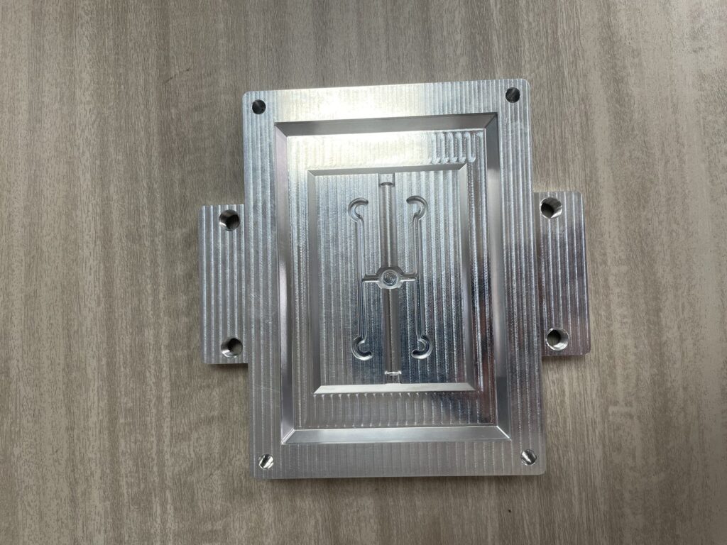
How to Polish Stainless Steel: Step-by-Step Shop Guide
Most guides to polishing stainless steel are written for someone holding an angle grinder. This one starts there too. The first half details the progressive hand-polishing sequence, tool setup, and step-by-step scratch removal, because that is what most searches are asking for. The second half explains what changes when that exact finish must be produced across a batch of hundreds or thousands of parts on a factory floor, which introduces an entirely different set of cycle time, geometry, and labor challenges.
If you already know your part is dull and want to diagnose why before you touch it, that route is covered separately. If you are choosing between finish grades rather than figuring out how to reach one, start with our guide on brushed vs satin vs mirror finishes. If your work centers on liquid chemical carriers and surfactants, consult our guide to stainless steel polishing chemicals. For operations weighing solid wax bars against liquid slurries, refer to our breakdown on stainless steel buffing compounds. The procedures below focus strictly on hands-on execution: setting up abrasive sequences, transitioning from manual tools to mass finishing equipment, and solving stubborn surface defects.
Before You Touch the Metal: What Are You Actually Trying to Fix?
Polishing changes the physical shape of a metal surface by cutting down high spots until light reflects evenly. If you grab an abrasive tool before identifying what is actually wrong with the metal, you will waste consumables, burn through labor hours, and risk ruining good parts. Dullness is rarely a single defect; it is a symptom caused by three distinct surface conditions.
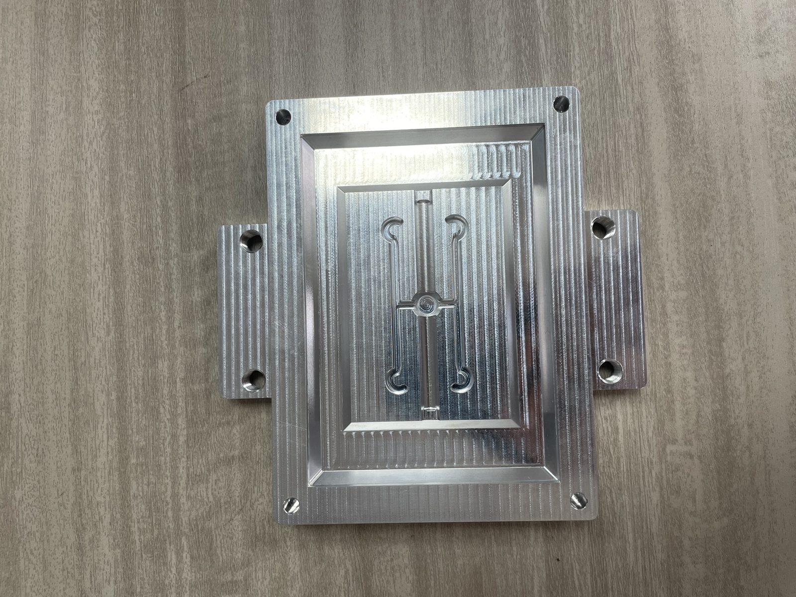
Three different problems people call "polishing"
Operators on the shop floor routinely mix up three very different surface issues under the general term "polishing":
- Surface Contamination and Oil Films: The underlying stainless steel is smooth, but reflection is blocked by dried cutting fluids, stamping lubricants, hard water spots, or shop dust. Applying a grinding disc or buffing wheel directly over dirty metal bakes oil into the grain, clogs abrasive belts, and glazes buffing wheels with black gunk.
- Superficial Scuffs and Handling Scratches: The part has shallow scratches from transport, sheet handling, or light assembly contact. The marks penetrate the passive layer but do not sit deep in the metal. These do not require aggressive stock removal; they need light blending or fine coloring.
- Deep Tool Marks and Mill Textures: Machining steps, CNC cutter paths, laser slag, or raised weld crowns leave distinct peaks and valleys. These physical ridges scatter light in every direction. Soft wheels and polishing paste will never flatten them. They require structured, step-by-step grinding to establish a flat baseline before any polishing can begin.
| Surface Condition | Damage to Base Metal | Required Shop Action |
|---|---|---|
| Dull haze, oil residue, fluid spots | None (surface film only) | Chemical degreasing, alkaline wash, and dry wipe |
| Light handling scuffs, hairline marks | Shallow surface penetration | Non-woven blending pad or fine color buffing |
| Tool cusps, heavy gouges, proud welds | Deep surface ridges | Multi-step progressive abrasive leveling |
The fingernail test — does the damage have depth?
Before mounting a disc or setting up a machine, run your fingernail across the defect at a right angle under light pressure. This simple tactile check gives you an immediate answer:
- If your nail glides smoothly without catching: The scratch is strictly superficial or sits within the surface oxide film. You do not need to grind away base metal. A solvent clean, fine non-woven hand pad, or light color buff will clear it.
- If your nail catches slightly: The scratch penetrates into the metal substrate. A soft cloth wheel will not buff this out. You must use an intermediate abrasive step to blend the furrow down flush.
- If your nail catches hard and stops: You have a severe gouge, deep cutter step, or unblended weld. Soft mops will only round the edges and highlight the defect. You must start with a coarse grinding step to flatten the metal before attempting to polish.
Which finish grade is your target? (brushed / satin / mirror)
A polishing run must target a specific engineering finish. A brushed finish relies on straight, parallel scratch lines produced by uniform abrasive belts or conditioning wheels. A satin finish requires a smooth, non-directional matte appearance with no grain lines, usually produced by tumbling media or orbital pads. A mirror finish demands the complete removal of all visible scratch patterns, creating an optically flat, reflective plane.
Trying to mirror-polish a part that only requires an industrial brushed look wastes shop time. Conversely, hitting a part with coarse abrasive when it was intended for a mirror finish introduces deep scratches that will take hours of extra work to blend out.
Where this step saves you money
Skipping surface diagnosis is an expensive habit. When an operator tries to buff out CNC mill marks using a soft wheel loaded with heavy compound, the wheel yields under pressure and dips into the valleys. The metal turns shiny, but the rippled surface remains, creating an ugly optical distortion known as orange peel. The part fails quality inspection.
On the other hand, grabbing coarse grinding paper to treat a surface that only needed degreasing cuts deep furrows into the metal. The operator then has to work through three or four extra abrasive stages just to remove their own self-inflicted grinding marks.
The Step-by-Step Hand Polish (the part you came for)
Manual polishing is the standard approach for custom fabrications, pipe assemblies, prototypes, and field maintenance. Getting a clean, commercial finish requires a strict abrasive progression, careful heat management, and zero contamination between stages.
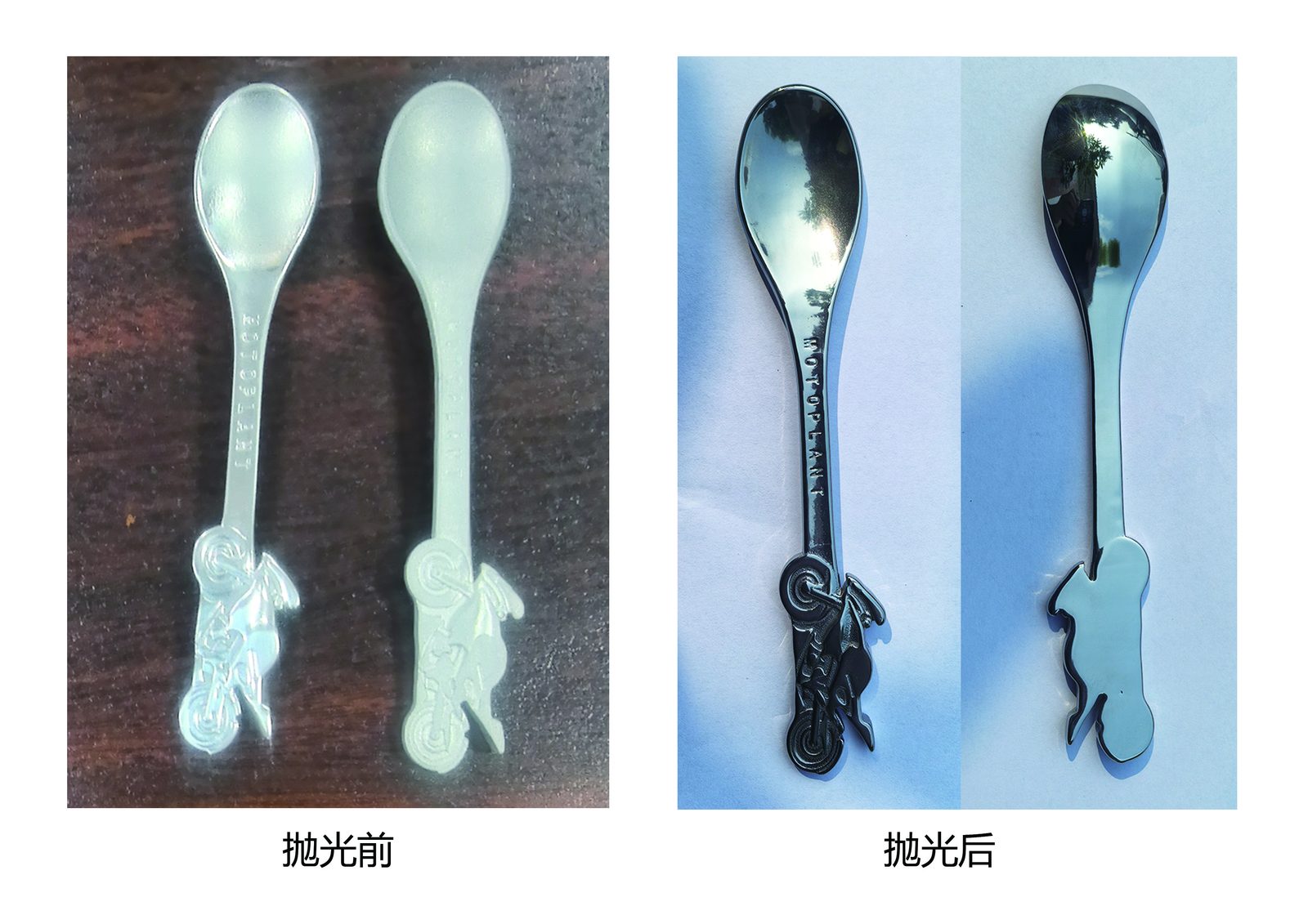
Step 1 — Degrease before anything else
Never let an abrasive wheel touch oily stainless steel. Machining coolants, stamping oils, laser plastic film residue, and fingerprints must be stripped off with a clean solvent wipe or hot alkaline wash.
If oil remains on the part, frictional heat turns the lubricant into a tacky paste. This paste loads the abrasive paper, packing the gaps between abrasive grains. Once loaded, the disc stops cutting metal and begins rubbing. This friction rapidly overheats the part, discolors the steel, and drags loose grit across the metal, creating wild rogue scratches that ruin your finish.
Step 2 — Establish your abrasive sequence (and why grit jumps fail)
Progressive polishing works on one fundamental rule: every single abrasive stage must completely erase the scratch marks left by the step before it. It cannot erase scratches from two steps back.
Select your initial abrasive based on your deepest defect. For tall weld seams or heavy gouges, start coarse. For raw cold-rolled sheet with minor handling marks, begin at an intermediate stage.
From your starting point, advance through abrasives in progressive steps. Do not take massive grit jumps. For example, jumping directly from a coarse leveling disc to a fine pre-buffing paper will fail every time. The fine paper quickly knocks off the peaks of the coarse scratches, making the surface look shiny under soft shop lights. However, the fine grit cannot reach down into the deep valleys. The moment you place the part under direct sunlight or inspection lamps, the coarse scratches reappear beneath the shine.
```
[Coarse Leveling] ────(90° Cross-Hatch)────> [Intermediate Blend] ────(90° Cross-Hatch)────> [Fine Pre-Buff]
```
To prevent this, change your tool path by 90 degrees on every single step. If your first pass moves vertically, run your next pass horizontally. Cross-hatching the grain allows you to visually verify that the new, finer pattern has completely replaced the older, coarser lines. Do not advance to the next step until every perpendicular mark from the previous run is gone.
Step 3 — Cut with a hard wheel
Once sequential sanding has brought the part to a uniform, fine-grit satin pre-polish, move to the cut-buffing stage. Cut buffing uses mechanical shear and micro-friction to level the microscopic sanding ridges.
Use a rigid contact wheel for this stage. A spiral-sewn cotton wheel or dense sisal wheel provides the firmness needed to bear down against work-hardened stainless steel without folding over. Apply a fast-cutting stainless compound bar to the spinning wheel.
Observe three strict shop practices during cut buffing:
- Keep the wheel moving: Traverse the part in smooth, overlapping passes. Never let the wheel dwell in one spot. Stainless steel holds heat locally and expands quickly. Holding the wheel in one position creates hot spots that warp sheet metal and produce blue thermal tint.
- Watch your wheel speed: Set your arbor speed to suit the wheel diameter. If the wheel spins too fast, excessive surface friction overheats the wax binder. Scorched compound turns into a hard, black crust on the wheel face. This crust stops cutting, chatters across the part, and bakes dark streaks into the metal.
- Match your pressure: Let the wheel and the compound do the mechanical cutting. Heavy downward force compresses the mop, generates heat, and wears out the wheel without improving cutting speed.
Step 4 — Colour with a soft wheel
Once cut buffing has produced a bright surface free of sanding lines, switch to color buffing. Color buffing does not remove baseline metal. Its purpose is micro-burnishing: smoothing the microscopic profile to produce high specular gloss and rich optical depth.
Mount a loose-fold, unstitched cotton wheel or soft canton flannel mop. Dress the wheel lightly with a fine coloring compound bar, such as a high-purity aluminum oxide or green chrome oxide formulation.
Use light contact pressure. For directional brushed parts, move strictly parallel to the grain. For mirror finishes, use gentle, overlapping circular passes to blend out directional tracks and eliminate wheel swirl.
Step 5 — Clean out the compound residue
A polishing job is not finished until all compound residue is removed. Buffing bars use binders made of animal fats, stearic acid, and industrial waxes. Frictional heat melts these binders, leaving a thin, sticky, water-repellent film that traps spent abrasive particles and metal dust.
Wiping this surface with a standard dry rag simply smears the wax around, leaving a cloudy haze that looks like a bad polish. Wash the part with a clean solvent or hot degreaser.
A trusted shop method is dusting the surface with dry calcium carbonate (whiting powder). Gently buff the powder off using a clean microfiber cloth. The fine powder absorbs the grease film and lifts away spent grit without scratching the mirror finish. Stripping this residue is also critical for downstream work: wax films ruin paint adhesion, foul weld joints, and prevent chemical passivation baths from reaching the base metal.
The one rule that decides whether you succeed: never skip a grit
If your finished metal looks hazy, uneven, or scratched, you almost certainly skipped an abrasive step. Trying to save five minutes by jumping over an intermediate grade forces you to spend thirty frustrating minutes on the buffing wheel. A soft cloth wheel loaded with fine compound cannot level parent metal. It simply polishes the hills and valleys of deep scratches, turning an honest grinding mark into a shiny furrow. Smooth, mirror-like stainless steel is earned step-by-step through consistent scratch refinement.
Why Hand Polishing Stops Scaling (and What That Costs You)
Handheld grinders and manual buffing lathes work well for small weld repairs, custom frames, and field touch-ups. However, when an operation needs to finish batches of hundreds or thousands of parts, manual polishing hits severe physical and financial limits.
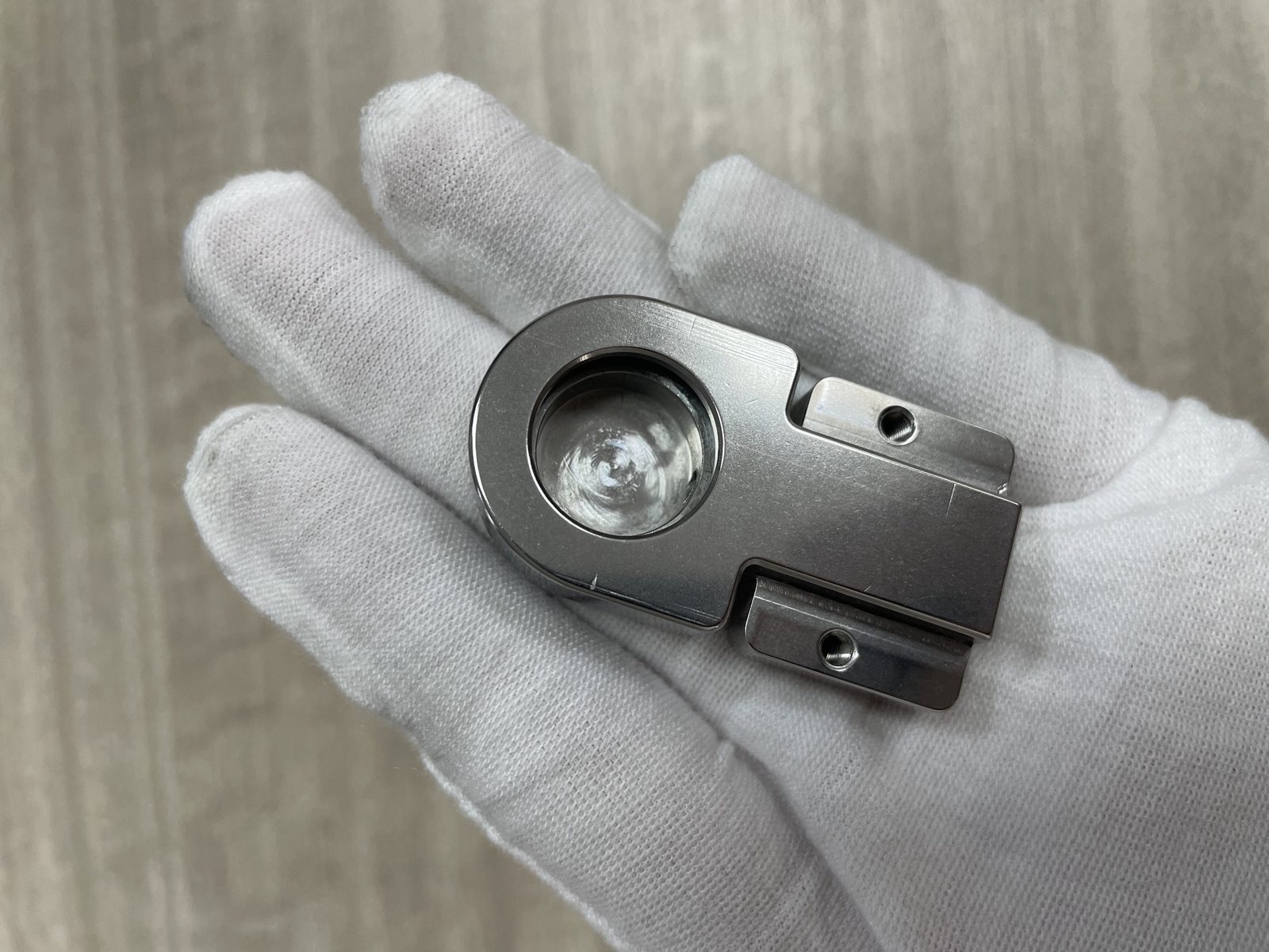
The three costs nobody puts on the offer
Cost estimates for manual polishing typically account only for direct labor hours. In practice, three hidden costs erode margins:
- Operator Fatigue and Inconsistent Speeds: Stainless steel is tough and work-hardens under pressure. Operating an angle grinder or bearing down on a buffing lathe is exhausting work. As an eight-hour shift progresses, operator fatigue slows cycle times, lowering total daily output.
- Scrap and Rework Rates: Manual finishing depends entirely on operator touch. A momentary slip, excessive dwell time that overheats the metal, or a slipped edge that gouges a finished surface can scrap an expensive part right at the end of the manufacturing line.
- Wasted Consumables: Hand buffing wastes significant compound and abrasive. Operators often overload wheels, slinging expensive wax onto the floor and walls. Flap discs wear unevenly during hand use and are often discarded before the abrasive is fully consumed.
Consistency: why two operators produce two finishes
Manual polishing cannot guarantee part-to-part consistency across different workers. If you hand identical parts, flap discs, and buffing bars to two different operators, they will apply different tool angles, feed speeds, and contact pressures.
Because stainless steel reacts directly to heat and mechanical force, the resulting finishes will not match. One worker will produce a deeper grain; the other will produce a shinier, lighter appearance. When these parts are mounted side-by-side on an architectural facade or commercial kitchen assembly, the visual difference is immediately obvious to the customer.
Complex geometry: where the buffing wheel physically cannot reach
A spinning wheel or flat disc only works along direct lines of sight. Handheld tools cannot reach:
- Deep, narrow internal bores and blind pockets.
- Intersecting holes, cross-drillings, and manifold ports.
- Internal bottom corners and tight fillet steps.
- Fine screw threads and internal gear teeth.
On components with intricate shapes, manual tools can only polish the outer faces, leaving inside corners and internal channels rough, dark, and unblended.
Edge rounding: the hidden damage of prolonged hand work
A serious downside of prolonged manual buffing is uncontrolled edge rounding. Cloth wheels and abrasive pads are flexible. When an operator buffs near a corner or flange, the wheel wraps around the edge, concentrating high friction along the corner.
Within seconds, crisp part edges, sharp sealing lands, and critical locating faces are rolled over into irregular curves. For precision machined parts that rely on clean edge breaks and strict geometric tolerances, this over-radiusing turns good components into scrap. Manual polishing has clear limits; recognizing them is the key to scaling your production.
The Batch Route: How the Same Result Is Made at Volume
To finish high volumes of parts without heavy manual labor, production shops transition to automated mass finishing systems. Instead of moving a tool across a clamped part, mass finishing submerges batches of loose or fixtured workpieces inside an active bed of abrasive media and liquid compound.
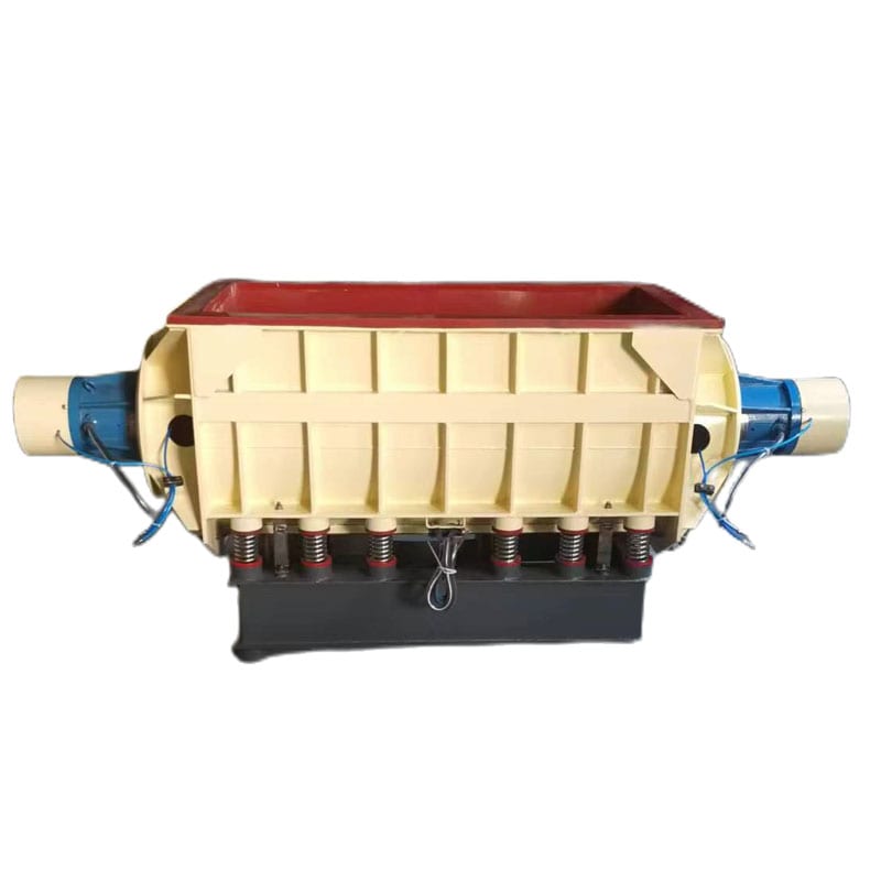
Vibratory finishing — what it replaces and what it cannot
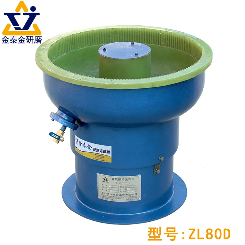
Vibratory finishing is the most widely used batch finishing method in manufacturing. Workpieces are loaded into a heavy-duty bowl or trough lined with durable polyurethane. Heavy eccentric weights mounted to an electric drive motor shake the chamber, causing the media and parts to circulate in a smooth, continuous roll.
This continuous scrubbing action deburrs edges, blends away CNC tool marks, and creates a uniform satin surface across an entire batch of parts at once. Standard vibratory finishing machines handle general stampings, brackets, and turned fittings. For long shafts, heavy profiles, or delicate parts that cannot tumble loosely without banging together, rectangular tub vibrators allow operators to drop in dividers or rigid holding fixtures.
Mass finishing, however, cannot do everything. It cannot spot-repair a small scratch on a large fabricated machine frame without processing the entire unit. Nor can it handle massive architectural panels, where wide belt sanders and manual polishers remain the correct choice.
Centrifugal barrel and disc — when you need more energy
When you are processing hard stainless alloys, need fast turnaround times, or require a near-mirror specular finish, the low-energy scrub of a vibratory tub is not enough. You need high-energy systems:
- Centrifugal Barrel Finishing: These machines operate like a planetary gear system. Several processing drums are mounted to a large central turret. The turret spins rapidly in one direction while the drums rotate in the opposite direction on their own shafts. This action creates high G-forces inside the drums, packing the media tightly against the parts and forcing them to slide across each other under heavy compressive load. Industrial barrel finishing machines excel at generating high-specular finishes on medical instruments, turbine blades, and precision hardware while protecting delicate features with internal racks.
- Centrifugal Disc Finishing: Featuring an open-top stationary chamber with a high-speed spinning disc at the bottom, disc finishing machines generate a rapid rolling vortex. Media and parts are driven up the stationary wall and fall back into the center. Processing speeds can be up to ten times faster than standard vibratory tubs, making them ideal for rapid deburring, radiusing, and pre-buff smoothing of small turned and stamped parts.
| Machine Category | Motion Profile | Kinetic Energy Level | Best Used For |
|---|---|---|---|
| Vibratory Bowl / Tub | Continuous helical rolling scrub | Moderate | General batch deburring, radiusing, uniform satin finishes |
| Centrifugal Disc | High-speed toroidal wall vortex | High | Rapid material removal and pre-buffing on small parts |
| Centrifugal Barrel | Planetary counter-rotation under G-force | Very high | Near-mirror luster, jewelry-grade finishes, precision parts |
| Rotary Tumbling Barrel | Cascading surface sliding plane | Low | Gentle processing of delicate parts and heavy steel burnishing |
Rotary barrel — the gentle option
The traditional tumbling barrel remains a reliable choice for sensitive or thin workpieces. Rotary barrel tumbling machines rotate hexagonal or octagonal drums at low, controlled speeds. As the drum turns, the load travels up the wall until it slides smoothly down the face of the mass.
Because abrasive cutting is confined to this sliding layer while the rest of the parts remain cushioned below, rotary barrels produce minimal impact damage. This makes them ideal for flat stampings that bend under vibratory pressure, as well as high-volume ball-burnishing with heavy steel media.
For tiny precision parts with micro-bores, high-speed magnetic finishing machines use magnetic fields to drive fine stainless steel pins through internal galleries, cleaning small internal details without changing outside dimensions.
Matching the machine to your part geometry
Choosing the right mass finishing machine depends on your component dimensions and structural rigidity. High-energy centrifugal barrels produce high-luster finishes quickly, but their drum dimensions limit part length. Long, slender parts require linear vibratory tubs with dividing plates to prevent part impingement. Thin stampings that fold under hydraulic action need the gentle slide of a rotary barrel or low-amplitude vibratory units. The goal is to match machine mechanics to your workpiece geometry.
Media and Compound: The Two Variables That Decide the Finish
In manual polishing, you control the cut using your abrasive belt and wheel. In mass finishing, your cutting tools are preformed abrasive media stones working with an aqueous chemical compound. The finish you get depends directly on how you pair these two consumables.
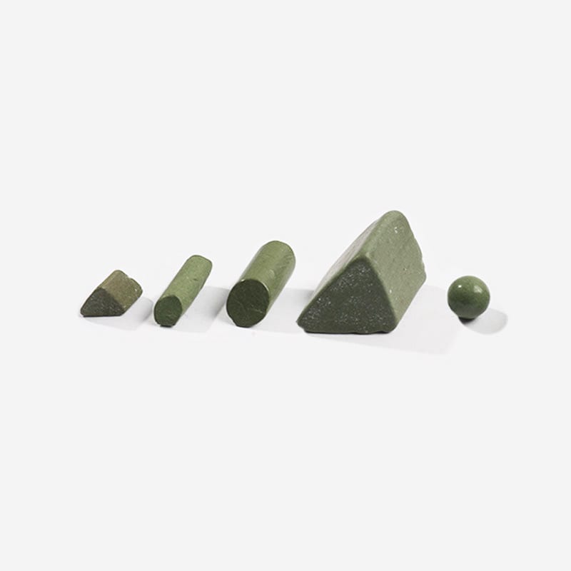
Media shape decides where the abrasive can reach
Media shape determines where abrasive contact occurs across the workpiece. Spherical and cylindrical shapes roll cleanly across wide, flat faces, delivering consistent surface smoothing. However, round media cannot reach into tight internal corners, narrow slots, or sharp steps.
Triangles, tri-stars, and angle-cut cylinders feature sharp corners that track directly into internal fillet radii, weld roots, and machined corners. Cones and pyramids provide balanced wear for parts that have both flat outer surfaces and recessed pockets. Choosing the wrong shape leaves outer surfaces finished while inside corners remain dull and discolored.
Media size decides whether it lodges in your holes
A common headache when finishing parts with holes, slots, or cavities is media lodging. When a media stone wedges into a hole, it stops moving, leaving that feature unpolished and forcing workers to spend hours picking stones out by hand.
To stop lodging before it starts, use this standard shop rule:
Maximum media dimension must be less than one-third of the minimum hole diameter.
Alternatively, choose media that is clearly larger than any opening on the part. Selecting media close to the size of your holes or slots guarantees lodged parts across the entire batch.
Ceramic, plastic, steel, and dry media — what each one is for
Matching media composition to your alloy and process step is essential for clean results:
- Ceramic Media: Made with aluminum oxide or silicon carbide grit bonded into a vitrified ceramic base. Ceramic media is dense and cuts fast, making it the industry standard for deburring, flattening CNC cutter marks, and blending weld beads. Review full grit formulations in our catalog of grinding media products.
- Plastic Media: Formulated with fine silica or alumina abrasives held in a polyester or urea resin. Plastic media is lighter and less aggressive than ceramic, providing a cushioned action that avoids part impingement. It produces a smooth, non-directional matte finish ideal for pre-buff preparation. For density and shape selections, check our vibratory media selection manual.
- Steel Media: Manufactured from through-hardened stainless steel shot in shapes like spheres, ball-cones, and pins. Steel media contains zero abrasive grains; its action is high-pressure compressive burnishing. It cold-works microscopic high points down into valleys, producing high specular luster without removing base metal. Inspect available shapes under our steel finishing media line.
- Dry Organic Media: Made from crushed walnut shell, corn cob, or hardwood granules treated with micro-fine polishing pastes. Running completely dry, this media generates gentle friction that warms the paste, yielding high specular clarity free of water spots or chemical stains. See carrier grades in our dry finishing media index.
| Media Family | Base Material | Working Mechanism | Process Stage |
|---|---|---|---|
| Ceramic | Vitrified clay with aluminum oxide | Fast abrasive cutting | Step 1: Deburring, tool-mark removal, weld leveling |
| Plastic | Polyester resin with fine abrasive | Cushioned micro-cutting | Step 2: Intermediate smoothing and pre-buffing |
| Hardened Steel | Solid stainless steel alloy | High-pressure compressive burnishing | Step 3: High-luster burnishing and surface hardening |
| Dry Organic | Crushed walnut shell or corn cob grit | Fine dry paste buffing | Step 3: High-clarity, water-free mirror finishing |
What the compound is doing (and what happens without it)
Wet mass finishing cannot run on plain tap water. The process requires chemical compounds that handle three critical tasks:
First, compounds provide controlled lubrication. The liquid forms a thin boundary layer between the media and the metal, cushioning impacts and ensuring abrasive grains cut cleanly rather than tearing or scuffing the steel.
Second, compounds suspend and flush out metal swarf. As the media cuts, fine metal particles and spent abrasive dust accumulate. Surfactants in the compound keep these micro-particles suspended in the fluid so they drain out of the bowl. Without proper compound, swarf settles back onto the parts, where the media peens it into the surface, turning the parts dark and cloudy.
Third, compounds clean and maintain passivation. Blended with chelating agents, mild organic acids, and corrosion inhibitors, the fluid dissolves free iron, cleans light oils, and protects the fresh metal from flash rusting. For specific alloy chemistry, consult our listings for industrial finishing compounds.
The three-stage sequence: cut, blend, brighten
High specular reflection in mass finishing is never achieved by simply tumbling parts longer in one machine. Running parts in cutting ceramic media for extended hours will not produce a mirror finish; it just reaches an abrasive balance where the ceramic keeps cutting its own matte texture into the metal.
A clean, reflective finish requires a disciplined, multi-step sequence:
```
[Stage 1: Cut] [Stage 2: Blend] [Stage 3: Brighten] Ceramic Media + Detergent Plastic Media + Surfactant Steel Shot or Dry Media Levels raw tool marks Smooths out ceramic scratch Burnishes surface to gloss
```
- Stage 1: Cut. Use fast-cutting ceramic media to level tool marks, take down weld crowns, and establish a uniform, flat matte base.
- Stage 2: Blend. Switch to fine plastic media or non-abrasive porcelain to remove the coarse ceramic scratches, bringing the metal to a fine, uniform satin surface.
- Stage 3: Brighten. Transfer parts to hardened stainless steel shot with a burnishing soap, or run them in dry walnut shell loaded with fine paste. This final step burnishes the smoothed surface into a deep, distortion-free luster.
Troubleshooting: What the Symptom Tells You
When a batch of stainless steel parts fails final visual inspection, do not make random machine adjustments. Diagnose the physical root cause and apply the correct fix.
| Problem | Root Cause | Shop Floor Check | Corrective Action |
|---|---|---|---|
| Bright but cloudy or milky finish | Skipped abrasive steps; swarf embedded in metal; compound film | Check under direct inspection lamp for fine scratches; solvent wipe | Go back one smoothing step; extend intermediate cycle; increase rinse flow |
| Uneven finish across different faces | Parts nesting together; media too large to enter recesses | Check part circulation; inspect if flat faces stick together | Lower batch volume; add anti-nesting media shapes; switch to smaller media |
| Yellow, straw, or blue surface tint | Overheating during manual buffing; excessive wheel speed or dry contact | Check if discoloration aligns with tool dwell spots | Lower arbor speed; reduce contact pressure; pickle and repassivate metal |
| Looks good wet, hazy and spotted when dry | Hard water minerals; slow drying; dirty rinse water drying on part | Wipe dried parts with a clean white cloth to check for white chalky film | Add deionized water rinse; dry parts immediately in a heated or spin dryer |
| Orange rust stains within 24 hours | Free-iron contamination; media shared with carbon steel tooling | Perform potassium ferricyanide test for free iron on the surface | Segregate stainless tooling; dump contaminated media; passivate parts |
| Rounded edges and washed-out part details | Excessive cycle time; overly heavy media; excessive hand pressure | Measure edge radii against CAD prints using an optical comparator | Shorten cycle duration; switch to smaller media; use protective fixtures |
The part looks bright but cloudy
A part that reflects light but looks milky or foggy has an optical clarity problem. The surface reflects light in scattered directions because microscopic scratches or oily films remain. In manual work, this means the operator jumped to color buffing before the cutting wheel had fully erased earlier sanding marks. In batch tumbling, it points to poor compound flow, dirty rinse water, or a media bed loaded with swarf that burnished metal dust back into the surface. Wipe the part with solvent to see if the haze is just an oily film. If the cloudiness remains in the metal, return to an intermediate smoothing stage.
One face is fine, another is not
When outside faces look good but inside pockets or back faces stay rough, the cause is geometric shielding or nesting. In vibratory tubs, flat parts often stick face-to-face, preventing media from flowing between them. Or, the media is simply too large to access tight recesses. Reduce your part loading, mix in different media shapes to break surface tension, or switch to a smaller media size that flows through internal channels.
The colour has gone yellow or blue
Visible color changes—from light straw to dark blue—indicate thermal damage. In hand polishing, this happens when an operator uses excessive pressure, runs a wheel too fast, or buffs without enough compound. Stainless steel holds heat locally. High friction causes thermal oxidation, forming a thick oxide layer that pulls chromium away from the surface and weakens corrosion resistance. Buffing over heat tint does not fix the metallurgy; the colored zone must be ground away or pickled off, followed by full chemical passivation.
It looked fine wet and hazy after drying
Parts that look clean when discharged from the tumbler but turn spotted and hazy after drying suffer from rinse and drying issues, not grinding faults. When hard water or compound solution dries directly on warm metal, dissolved mineral salts and soap residue precipitate across the surface. Rinse parts thoroughly with clean water—using reverse-osmosis or deionized water where available—and dry them immediately using heated vibratory dryers or centrifugal spin dryers before water can evaporate on the metal.
Rust appeared within a day
When stainless steel develops surface rust spots within hours of polishing, the culprit is free-iron cross-contamination. If grinding wheels, wire brushes, or tumbling media previously used on carbon steel are used on stainless steel, free-iron particles become embedded in the stainless surface. When exposed to humidity, these iron particles rust immediately, creating galvanic cells that pit the stainless steel. Keep all stainless finishing tools, wheels, and media strictly separated from carbon steel work, and run finished parts through a chemical passivation bath to strip away surface iron.
How to Check the Result Before You Ship
Never ship polished stainless steel parts based on a quick glance under general shop lights. Quality control must follow clear, repeatable checks to ensure the surface meets drawing requirements.
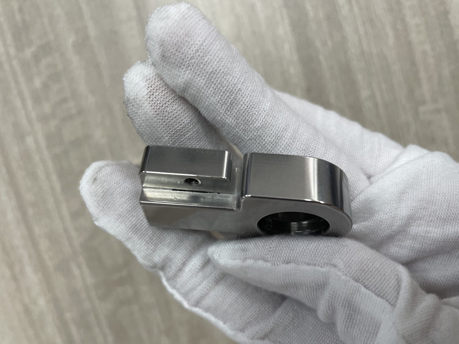
Visual check against a retained sample
The most practical quality control check is side-by-side comparison with an approved physical master sample. Human perception of gloss and reflection shifts under varying shop lighting. Conduct inspections inside an inspection booth equipped with standard, color-balanced lighting. Hold the production part and the master standard at identical angles, checking both direct reflection and low-angle glare to verify gloss level, scratch pattern uniformity, and color consistency. For detailed classification grades, see our breakdown in the surface grade guide.
What to ask for when you need a measured number
When customer prints demand measurable surface metrics rather than visual approval, quality control uses calibrated shop instruments:
- Stylus Profilometry: A calibrated diamond-tipped stylus tracks across the surface over a set evaluation distance to measure micro-roughness. On directional brushed parts, always measure perpendicular to the grain to capture true peak-to-valley profile variance.
- Optical Glossmeters: For mirror and high-specular finishes, profilometry alone does not fully reflect visual sharpness. Calibrated glossmeters shine a standard light beam at a set angle and measure the percentage of light returned to an internal sensor, giving you a precise number for surface reflectivity.
Do not guess at customer expectations. Ask your client's engineering team for their exact inspection parameters and acceptable reading ranges before running production.
The inspection record that ends arguments
To protect your shop from disputes, document every production batch with a simple, signed inspection record. A clean quality report should record:
- Material heat number, alloy grade, and incoming surface state.
- Master sample tracking ID and drawing revision number.
- Machine unit ID, media charge details, and compound lot number.
- Instrument calibration verification, profilometer readings, and gloss measurements.
- Inspector signature and date of release.
Frequently Asked Questions
1. Can I polish stainless steel by hand at home?
You can remove superficial water spots, light handling marks, and mild tarnishing by hand using a microfiber cloth, non-woven scouring pad, and a quality stainless polishing paste. However, leveling deep tool marks, removing heavy scratches, and producing a true mirror finish cannot be done by hand rubbing alone. Stainless steel is a hard, work-hardening metal. Cutting down base metal and leveling the surface profile requires continuous mechanical speed and pressure that can only be supplied by powered tools like angle grinders, variable-speed polishers, or tumbling machines.
2. What grit should I start with?
There is no single correct starting grit. Your starting abrasive is determined entirely by the depth of the deepest flaw on the workpiece. If you are blending heavy weld beads or deep handling gouges, start with a coarse leveling abrasive to bring the defect flush with the surrounding parent metal. If you are working with clean, cold-rolled sheet that only has light scuffs, start with an intermediate abrasive. The goal is to start with the finest grit capable of leveling the primary defect, which prevents putting unnecessary deep scratches into the metal that you will have to grind out later.
3. Why does my stainless steel look worse after polishing?
Stainless steel usually looks worse after polishing because of skipped abrasive steps or excessive heat. If you jump from a coarse grinding disc to a fine coloring wheel, the wheel will make the metal shiny while leaving coarse scratches trapped beneath the gloss. Under direct light, these scratches look worse than they did on the raw metal. Additionally, applying heavy pressure or running tools at high speeds overheats the metal, producing yellow or blue heat tint, or scorching compound into a dark residue that smears across the workpiece.
4. Can polishing remove deep scratches?
Mechanical polishing can remove scratches of any depth, provided you are allowed to remove enough base metal to bring the surrounding area down flush with the bottom of the scratch. On thick plates and heavy weldments, stock removal is normal practice. However, on precision machined parts with tight dimensional limits, or on thin sheet metal, heavy grinding will take the part out of tolerance or cause visible buckling and oil-canning. On thin or precision parts, deep scratches often cannot be polished out without scrapping the component.
5. Does polishing stainless steel remove the protective layer?
Grinding, sanding, and buffing physically strip away the microscopic chromium oxide film that gives stainless steel its corrosion resistance. Once clean stainless steel is exposed to atmospheric oxygen, this passive layer begins reforming naturally. However, natural air passivation takes time and can be blocked if grease, buffing wax, or embedded iron particles remain on the surface. For parts installed in marine, chemical, or sanitary food environments, relying on air passivation is risky. Polished parts should undergo chemical passivation in a nitric or citric acid bath to clean off tramp iron, remove compound traces, and rapidly restore a strong, uniform passive layer.
6. How long does it take to polish a batch of parts?
Cycle times in mass finishing depend on the incoming surface roughness, alloy hardness, media aggressiveness, machine energy density, and media-to-part ratio. A high-energy centrifugal barrel machine can achieve in minutes what a conventional vibratory tub or rotary barrel takes hours to deliver. Cycle times should never be guessed or based on general claims; they must be determined through pilot testing on your actual production parts to establish a repeatable, stable shop window.
Clarifying Equipment Configuration and Sourcing Specifications
When transitioning from manual grinding to automated mass finishing systems, engineering and purchasing teams should clarify machine parameters before finalizing equipment orders:
- Part Dimensions, Weight, and Output: Confirm whether your parts and daily batch weights require an open-bowl circular vibrator, an elongated linear trough, or an enclosed centrifugal barrel system.
- Chamber Volume and Part Separation: Calculate total tub volume to ensure an adequate media-to-part ratio, preventing parts from hitting each other during high-frequency vibration.
- Compound Metering and Drainage: Check that the machine includes an automated liquid dosing pump and proper drainage channels to continuously flush suspended metal fines from the media bed.
Review our full index of industrial finishing machines to evaluate equipment footprints, drive systems, and electrical requirements against your facility layout. For detailed questions regarding fixture design, batch testing, or automation options, reach out directly through our technical engineering contact page. Establishing your parts, media choices, and machine kinematics in advance ensures smooth commissioning on your shop floor and reliable, repeatable surface quality on every run.
 +86-592-2381506


 IPv6 network supported