Automated Deburring Machines: Architecture, Tolerances, and Payback
Manufacturing facilities transitioning away from manual deburring benches face a familiar dilemma. Manual deburring with rotary files, scotch-brite pads, and hand deburring blades creates erratic edge breaks, operator fatigue injuries, and erratic scrap rates on high-value CNC machined parts, stampings, and die castings. Yet when manufacturing engineers search for automated deburring machines, they are routinely confronted with generic marketing summaries that fail to address fundamental shop-floor realities: Which machine architecture actually matches their workpiece geometry? How do automated systems prevent over-cutting critical sealing faces? What are the realistic cycle times and consumable lifespans? And how is capital expenditure amortized against manual labor?
An automated deburring machine is not a single generic device. It represents an integrated system designed to deliver controlled mechanical cutting force to micro-burrs and parted edges without degrading core dimensional tolerances.
This technical guide examines the four dominant automated deburring machine architectures, analyses the mechanics of dynamic force compliance and edge radiusing ($R0.1 \sim R0.4\text{ mm}$), presents an abrasive media matching matrix, details cycle time and material handling integration, outlines a quantifiable ROI payback model, and provides an empirical shop-floor troubleshooting matrix.
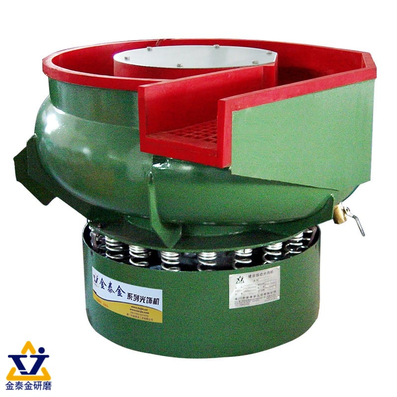
Four Architectural Classes of Automated Deburring Machines
Selecting an automated deburring machine begins with component geometry, alloy hardness, batch volume, and part fragility. The four primary equipment families utilized in modern automated finishing cells differ fundamentally in their kinetic energy transfer and workpiece holding methods.
1. Continuous and Batch Vibratory Systems with Automatic Internal Separation
Vibratory mass finishing remains the workhorse of industrial batch deburring. In automated circular bowl configurations — exemplified by machines such as the ZL300C (catalogue capacity rating 300 L) and ZL600C — a heavy-duty unbalanced eccentric motor induces an upward helical rolling motion across an annular, polyurethane-lined processing channel.
- Automation Mechanism: During the active deburring phase, an internal polyurethane dam or pneumatic flap remains retracted, allowing the media-workpiece charge to circulate continuously. When the PLC process timer expires, the pneumatic gate pivots into the channel. The moving mass climbs an integrated spiral ramp onto a perforate separation screen deck.
- Separation and Rinse: Media pellets fall through the screen apertures back into the lower bowl, remaining ready for the subsequent batch. Deburred workpieces travel forward over the screen under residual vibratory impulse, passing beneath freshwater spray bars to remove residual abrasive swarf before exiting onto a conveyor or wash station.
- Best Suited For: Stamped steel brackets, aluminum automotive housings, brass fittings, turned pins, and transmission gears where batch volumes range from hundreds to thousands of parts per shift.
For a comprehensive comparison between vibratory bowl and trough configurations, consult our technical overview on deburring machine route selection.
2. High-Speed Centrifugal Disc (Vortex) Finishing Machines
Where vibratory cycles requiring 45 to 90 minutes conflict with fast takt times, automated high-speed centrifugal disc machines — such as the OBD-LLF120 or LLB50 — accelerate stock removal by a factor of 8 to 12 times compared to conventional vibration.
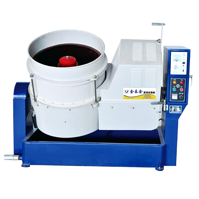
- Automation Mechanism: The machine features a stationary vertical container with an independently driven rotating spinner disc at the base, separated by a high-precision adjustable seal gap ($0.05 \sim 0.3\text{ mm}$). Centrifugal force drives the mixture outward and up the wall, folding back inward to create a violent toroidal vortex. Modern automated disc cells incorporate motorized electric tilting frames to dump the entire charge onto an external vibratory separator at cycle completion.
- Best Suited For: High-volume stampings, thin washers susceptible to flat-on-flat adhesion, surgical instruments, and CNC turned fasteners requiring cycle times under 20 minutes.
Review the operational parameters and gap management rules in our guide to disc finishing machine technology.
3. Programmatic Magnetic Pin Deburring Systems
Conventional tumbling media cannot enter blind threaded holes, cross-drilled hydraulic intersecting ports, or micro-fluidic slots below 1 mm without wedging. Automated magnetic deburring machines — including the OBD-30, OBD-60, and OBD-100 series — resolve this through non-contact electromagnetic agitation.
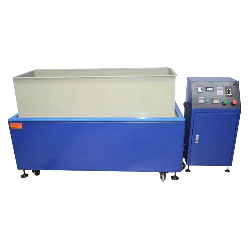
- Automation Mechanism: A high-speed multi-pole magnetic field spins beneath a stationary water-filled chamber at 0 to 1,800 RPM. Fine SUS304 magnetic stainless steel pins (available in diameters from 0.2 mm to 1.2 mm) align with the alternating magnetic flux lines, acting as millions of microscopic chisels that strike external burrs and internal cavities simultaneously. Programmatic PLC controls automatically reverse field direction every 60 to 120 seconds to prevent pin shadowing and dead zones.
- Workpiece Capacity: From 30 kg in the OBD-30 up to 100 kg in the OBD-100 (catalogue ratings; confirm against workpiece dimensions and specific gravity before planning production throughput).
- Limitation: Operates strictly on non-ferromagnetic or weakly magnetic alloys (austenitic stainless steels, aluminum, brass, copper, titanium, and engineering plastics). Ferromagnetic carbon steels or 400-series martensitic alloys will clump together and cannot be processed in magnetic fields.
For in-depth analysis on magnetic pin fluidics, review our engineering guide to magnetic polishing machines when loose media cannot reach.
4. Long-Stroke Linear Trough Vibrators for Large Structural Components
Large workpieces that cannot tumble freely inside a circular bowl without striking walls or each other require heavy linear trough machines, such as the L1300 (nominal trough capacity 1,200 L), L1500 (1,500 L), or L1800 (1,800 L).
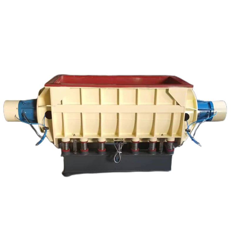
- Automation Mechanism: Twin out-of-balance motors (e.g., dual 5.0 kW to 7.5 kW drives) mounted at opposite ends induce a linear scrubbing wave throughout the entire media bed. Automated installations feature overhead programmable gantry hoists that lower part baskets directly into the fluidized ceramic bed, timing the immersion cycle before withdrawing the deburred payload to an adjacent automated rinse and dryer station.
- Best Suited For: Aircraft structural spars, automotive powertrain casings, manifold blocks, and aluminum extrusions up to 2.5 meters in length.
Explore structural equipment boundary lines in our reference on deburring equipment forms and the tool boundary.
Force Compliance and Edge Radiusing: Preventing Over-Cutting on Precision Tolerances
The most critical apprehension among manufacturing and quality assurance engineers regarding automated deburring is dimensional wash-out: Will the machine erode sharp sealing edges, enlarge reamed hole diameters, or violate tight geometric dimensioning and tolerancing (GD&T) callouts?
```
Manual Bench Deburring (Rigid / Operator-Dependent): Hand Pressure: 40 N ~ 120 N (Uncalibrated) ──► High Edge Gouging Risk ──► Cpk < 1.0
Automated Mass Finishing (Dynamic Compliance): Hydrodynamic Bed Resistance: 5 N ~ 45 N (Continuous) ──► Uniform Edge Radius R0.1~0.3mm ──► Cpk ≥ 1.33
```
Kinetic Contact Pressure vs. Rigid Tool Engagement
In manual hand-deburring or rigid CNC spindle deburring, the tool path is fixed in space. If a cast or stamped part arrives with $+0.3\text{ mm}$ raw stock deviation, a rigid chamfer mill will take a heavy cut, creating a gouged flat or excessive chamfer. Conversely, if the part is undersized, the rigid tool misses the burr entirely.
Automated loose-abrasive mass finishing utilizes inherent fluid-bed compliance:
- Distributed Energy Transfer: Rather than concentrating cut forces at a single point, kinetic energy is distributed across thousands of media pellets suspended in an aqueous compound surfactant.
- Contact Force Thresholds: The normal contact force exerted by an individual ceramic or plastic pellet during bowl circulation ranges from approximately $5\text{ N}$ to $45\text{ N}$ (typical industry reference values; dynamic contact force varies by media bulk density, bowl amplitude, and fluid viscosity). This level of force easily shears away delicate burr roots ($0.02 \sim 0.1\text{ mm}$ thickness) where stress concentration is extreme, but cannot deflect or abrade flat structural planes with broad surface areas.
- No Tool Mark Gouging: The rolling, randomized contact eliminates directional cutter chatter, transforming micro-burred edges into homogeneous radial breaks.
Controlling Edge Radius ($R0.1 \sim R0.4\text{ mm}$) Without Violating Sealing Land Flatness
Engineering drawings frequently specify edge breaking requirements, such as $R0.10 \sim R0.25\text{ mm}$ or $C0.1 \sim C0.3\text{ mm}$, accompanied by strict flatness limits on milled gasket faces (e.g., flatness within $0.02\text{ mm}$).
- The Media Bulk Density Factor: High-density ceramic media ($2.4 \sim 2.7\text{ g/cm}^3$) generates high compressive pressure, producing edge radii rapidly (typically $0.05\text{ mm}$ radial increase every 15–20 minutes under standard vibratory action). However, on soft alloys like ADC12 or 6061-T6 aluminum, heavy ceramic can peen part edges or peen burrs backward into the root.
- The Low-Density Resin Alternative: Synthetic polyester or urea-plastic media ($1.5 \sim 1.8\text{ g/cm}^3$) cushions part contact. The edge radiusing progression is more gradual ($0.02 \sim 0.04\text{ mm}$ per 30 minutes), allowing precise process cutoff when the target edge break is achieved, without rounding mating seal lands.
- Process Verification: Production engineers should establish Cp/Cpk metrics ($Cpk \ge 1.33$) by taking 30-piece sample runs, measuring edge radii under a 50× optical shadowgraph or contour measuring system, and logging mass loss per cycle.
For deeper insights into media sizing and corner radiusing, review the vibratory tumbler media selection guide.
Abrasive Media and Chemistry Selection Matrix for Automated Cycles
Automated deburring machines rely on the synergy between the mechanical drive, the abrasive pellet geometry, and the chemical compound solution. Charging the incorrect combination produces glazed media, oxidized workpieces, or lodged stones.
The following matrix provides verified matching guidelines across common industrial alloy groups:
| Substrate & Workpiece Type | Target Burr Characteristic | Recommended Media Geometry & Composition | Verified Chemical Compound | Typical Automated Machine Platform |
|---|---|---|---|---|
| 304 / 316 Stainless Steel (Laser cut brackets, CNC manifolds) | Heavy cut edge burrs ($0.05 \sim 0.15\text{ mm}$), heat-tint scale | Brown fused alumina ceramic triangle or angle-cut triangle (fast-cut grade) | compound-JTJ20 (acidic descaler & deburring booster) | Automated vibratory bowl with separation screen (ZL300C / ZL600C) |
| ADC12 / A380 Aluminum Die Castings (Gearbox covers, pump housings) | Parting line flash, CNC face mill exit burrs | Synthetic polyester-bonded plastic cones or angle-cut triangles ($120\# \sim 240\#$) | compound-LC10 (neutral/mildly alkaline deburring & degreaser) | High-speed centrifugal disc (OBD-LLF120) or vibratory bowl |
| 6061-T6 / 7075 Aluminum (Structural brackets, aerospace links) | Delicate milled profile burrs, tight corner radii ($< R0.2\text{ mm}$) | High-alumina porcelain cylinders or fine-mesh plastic media | compound-LC10 (prevents surface smearing and black ash) | Automated vibratory bowl (ZL150 / ZL300C) |
| Precision Brass & Bronze (Fluid valves, hydraulic fittings, nozzles) | Thread root feather burrs, cross-hole drill exits | Fine ceramic cylinders ($3 \times 3\text{ mm}$) or SUS304 magnetic pins ($0.5\text{ mm}$) | compound-LC10 / Mild brightening surfactant | Automated magnetic deburring machine (OBD-35 / OBD-60) |
| Carbon Steel / Alloy Steel (Transmission gears, forged shafts) | Heavy hobbing burrs, stamping break edges | Fast-cutting vitrified ceramic angle-cut stars or triangles | compound-JTJ25 (universal coarse deburring) followed by rust inhibitor | Heavy circular vibratory bowl or linear trough (L1300) |
| Micro Turned Fasteners / Pins (Medical screws, connector contacts) | Micro-burrs in internal threads ($< M3$) and slots | Magnetic stainless steel pins ($0.2 \sim 0.5\text{ mm}$ diameter) | Dilute neutral surfactant wash | Automated magnetic deburring machine (OBD-30) |
Note: All chemical compound designations (compound-LC10, compound-JTJ20, compound-JTJ25) represent verified factory formulations designed to sustain abrasive cleanliness, accelerate oxide breakdown, and keep metal swarf in aqueous suspension.
For chemical compound properties and alloy matching rules, consult our guide on metal compounds for aluminium versus steel.
Cycle Time, Takt Time Integration, and Line Balancing
When incorporating automated deburring equipment into existing manufacturing cells, line designers must synchronize deburring cycle times with upstream machining or stamping takt times.
```
Upstream CNC Milling Cell (Takt: 90 s/part) └──► Accumulation Buffer (40 parts / 60 min) └──► Automated Vibratory Deburring Batch (ZL300C: 45 min cycle) └──► Auto-Separation Screen Deck (3 min discharge) └──► Centrifugal Dryer 35A (5 min hot-air spin dry) └──► 100% Final Inspection / Packaging
```
Batch Processing vs. In-Line Continuous Flow
Manufacturing setups utilize two main automated balancing strategies:
- Cellular Batch Accumulation: A machining cell of 4 to 6 CNC machining centres outputs one finished workpiece every 90 seconds. Finished parts collect on an accumulation conveyor or wash tote. Once an economic batch size (e.g., 40 to 80 parts) accumulates, an operator or pick-and-place robot charges the entire batch into a ZL300C vibratory bowl. Because the deburring cycle runs unattended for 45 minutes, a single operator manages machining, deburring, and packaging without bottlenecking the line.
- High-Speed Disc Indexing: Where floor buffer space is constrained, a high-speed centrifugal disc unit (OBD-LLF120) operates on short 12-minute cycles. Smaller batches are charged and discharged rapidly, matching the hourly output of high-speed stamping presses.
Material Handling and Automatic Separation Mechanics
The real efficiency of an automated deburring machine is determined by what happens at cycle completion. Manual scooping or hand-sifting destroys productivity.
- Internal Screen Classification: In vibratory bowls with integrated separation decks, an electro-pneumatic gate drops into the channel. The vibration drives the load across an interchangeable polyurethane or stainless steel screen.
- Screen Sizing Principle: If the workpiece is larger than the media, the screen apertures must be $2 \sim 4\text{ mm}$ larger than the media pellet's maximum cross-section, but smaller than the workpiece's smallest dimension. Media drops back into the bowl while workpieces advance to the exit chute.
- Inverse Separation: When deburring tiny screws or rivets that are smaller than the media pellets, the screen openings are selected to let workpieces pass through into a discharge hopper while the larger media remains on top of the deck.
- Downstream Drying Integration: Freshly deburred and rinsed wet parts must be dried immediately to prevent atmospheric oxidation and water-spotting. Automated lines route discharged parts directly into a heated centrifugal industrial dryer — such as Model 35A (35 kg load, 1.8 kW heating) or Model 70A (60 kg load, 3.0 kW heating) — where high-speed spin drying flashes off surface moisture within 3 to 5 minutes.
For technical details on moisture control, read centrifugal dryer: why drying is a process step.
Equipment Investment, Consumable Lifespan, and ROI Calculation Model
Building a financial business case for automated deburring machinery requires evaluating initial capital expenditure (CAPEX), recurring tooling/media wear (OPEX), and direct labor savings.
Capital Expenditure (CAPEX) vs. Operational Expenditure (OPEX)
- CAPEX Overview (Industry Baselines): Standalone semi-automated vibratory finishing bowls with internal separation (such as the ZL300C) typically represent capital investments in the range of $12,000 to $28,000, depending on bowl capacity, polyurethane lining grade, sound enclosure, and pneumatic gate automation. High-speed centrifugal disc units and fully automated multi-stage lines with conveyors and dryers range between $25,000 and $65,000.
- Consumable Wear Rates: Media does not last indefinitely. High-grade vitrified ceramic deburring media exhibits an average wear rate of approximately $0.2\% \sim 0.8\%$ by weight per processing hour (under standard vibratory conditions). Plastic media exhibits wear rates of $0.5\% \sim 1.5\%$ per hour. Compound consumption typically runs at a lean $1\% \sim 3\%$ concentration in the water dosing stream.
- Abrasive Replacement Budgeting: Consumable costs generally contribute less than $0.02 to $0.06 per finished workpiece, compared to manual hand-finishing consumables (flapper wheels, carbide burrs, sanding belts) which routinely cost $0.20 to $0.60 per workpiece.
The Shop-Floor Amortization Formula
The return on investment (ROI) period is calculated by comparing manual bench labor against automated machine operation:
$$\text{Payback Period (Months)} = \frac{\text{Total Installed Machine CAPEX}}{(\text{Direct Labor Saved} + \text{Scrap Reduction Value}) - (\text{Media \& Power OPEX})}$$
Practical Financial Scenario:
- Current State: A mid-sized precision machining facility employs two full-time deburring bench workers across two shifts. Direct labor cost equals $6,500/month (including benefits and overhead). Manual scrap/rework from edge gouging averages $800/month. Total monthly manual cost: $7,300.
- Automated Alternative: Installing a ZL300C automated vibratory deburring bowl with auto-screen separation ($22,000 installed). Operating one hour of operator staging time daily plus electrical power and ceramic media wear totals $750/month.
- Net Monthly Savings: $\$7,300 - \$750 = \$6,550/\text{month}$.
- Calculated Payback Period:
$$\frac{\$22,000}{\$6,550} \approx 3.36 \text{ Months}$$
Even under conservative utilization scenarios where machine usage is only 50% of capacity, automated deburring systems typically amortize fully within 6 to 12 months, while eliminating chronic workplace ergonomic and repetitive strain liability.
For guidelines on vetting machinery vendors, review how to vet deburring machine manufacturers.
Shop-Floor Troubleshooting Matrix: Diagnosing Automated Deburring Defects
When an automated deburring process yields sub-standard parts, process engineers should consult this four-column diagnostic matrix to isolate root causes:
| Observed Defect / Problem | Probable Root Cause | Verification Method | Corrective Action |
|---|---|---|---|
| Peened / Rolled Burrs (Burr flattened against parent metal instead of severed) | 1. Media too large or bulk density too high.<br>2. Vibratory amplitude excessive.<br>3. Parting flash too thick for loose-abrasive mass action. | Inspect burr root under 30× magnification; verify whether root is fractured or folded over. | Switch from heavy ceramic to fine-cut plastic media; reduce motor vibration amplitude; verify upstream cutting tool sharpness to minimize heavy burr formation. |
| Edge Over-Radiusing (Critical bearing lands or seal faces rounded beyond drawing tolerance) | 1. Cycle duration run far past deburring endpoint.<br>2. Media abrasive grit size too aggressive.<br>3. Media-to-part ratio too low. | Check edge profile on optical comparator; measure dimensional stock loss across cycle intervals. | Shorten deburring cycle timer; change from coarse cutting grade to medium/fine polishing media; increase media-to-workpiece volumetric ratio to at least 3:1. |
| Media Lodging / Wedging (Abrasive stones trapped inside internal holes or blind slots) | 1. Media pellet dimension matches workpiece feature dimension ($\pm 10\%$).<br>2. Worn media reduced to critical lodging size. | Gauge diameter of wedged stones against part aperture drawing. | Enforce the One-Third / Three-Times Rule: media must either be $< 1/3$ or $> 3 \times$ the critical hole diameter; regularly screen out undersized worn media pellets. |
| Surface Staining / Flash Rusting (Parts exit the discharge deck with grey, black, or oxidized discoloration) | 1. Inadequate chemical compound dosing.<br>2. Water hardness salts precipitating into micro-pores.<br>3. Delayed downstream drying. | Check pH of drain discharge ($7.5 \sim 9.0$ for steel, $6.5 \sim 8.0$ for aluminum); monitor transfer time to dryer. | Increase dosing of compound-LC10 (or compound-JTJ25); clean bowl drain filters; ensure immediate hot-air spin drying in a centrifugal dryer. |
| Slow Deburring Rate / Glazed Media (Cycle times double without achieving burr detachment) | 1. Abrasive micro-pores saturated with oil and metal swarf.<br>2. Water flow rate insufficient, creating thick mud slurry. | Touch media pellet face: if slippery and polished glassy smooth, media is glazed. | Run a 30-minute self-cleaning cycle with fresh ceramic and heavy-duty degreaser (compound-LC10); increase clean compound flushing volume during production cycles. |
For volumetric charging practices that protect yield, review our technical guide on loading ratio: the variable that decides yield.
Boundary Limitations: When Automated Mass Deburring Does Not Apply
Automated mass finishing machines are exceptionally efficient, but they do not solve every burr problem. Recognizing the technical boundaries of the technology prevents costly capital misallocations.
- Heavy Thermal Plasma / Oxy-Fuel Cutting Slag:
Loose abrasive media relies on friction and dynamic kinetic impact. Heavy slag dross ($> 1.5\text{ mm}$ thick) welded to thick flame-cut plate cannot be removed by vibratory media. It requires primary mechanical grinding, wide-belt slag grinders, or manual chisel descaling before secondary vibratory edge radiusing.
- Ultra-Large Single Weldments Exceeding Trough Geometry:
Workpieces exceeding 2.5 meters in length or weighing more than 1,500 kg cannot circulate inside standard vibratory bowls or troughs. These components require dedicated overhead gantry brushing heads or automated 6-axis robotic deburring arms equipped with force-controlled compliant spindles.
- Capillary Micro-Fluidic Channels ($< 0.3\text{ mm}$):
Internal passages in medical HPLC valve manifolds or diesel fuel injector nozzles cannot be penetrated by solid ceramic, plastic, or magnetic media without catastrophic lodging. These features require Thermal Energy Method (TEM) deflashing or Electrochemical Deburring (ECD).
- Directional Cosmetic Grain Requirements:
Automated mass finishing produces an isotropic, non-directional matte or semi-bright surface finish. If an architectural panel or consumer electronics faceplate specifies a linear brushed hairline finish (e.g., #4 brush), it must be finished on a pass-through wide-belt or stroke sanding machine.
Verified Machine Specifications and Quality Certifications
All automated deburring equipment manufactured by our facility in Xiamen, China (established in 1992) complies with rigorous international manufacturing and safety standards:
- CE Machinery Directive Compliance: Certified under European CE standards across both vertical and horizontal platforms:
- Certificate M.2023.206.C88121 (Vertical platforms; valid through 2028-07-24; test reports DTT230706S005 / S006) covering models including LX80B, CJS480A, CJS320, CJG480A, CJG320, BJ160B, BLG400, and BLG200.
- Certificate M.2023.206.C88120 (Horizontal & Vibratory platforms; valid through 2028-07-24; test reports DTT230706S003 / S004) covering models including ZL150, ZL300, ZL450, HG70A, WFX50B, LLG40, LLQ120, YH-680D, YG350, YG450, HBPG-01, HBPG-02, and GSLX-120 (totaling 21 distinct verified machine models).
- ISO 9001 Quality Management Certification: Valid under Certificate 00726Q01571R001 issued by Zhongjian Certification Co., Ltd. (certified through 2029-06-02) for the production and sales of surface finishing and polishing machinery.
- Intellectual Property: Backed by 24 granted Chinese intellectual property rights, including 1 invention patent, 17 utility model patents, and 6 industrial design patents.
Empirical Sample Testing and Trial Verification
Because edge geometries, burr root thickness, and alloy hardness vary between manufacturing lots, production parameters should always be verified empirically before finalizing equipment orders.
We invite engineering teams to submit production drawings and raw sample workpieces to our technical finishing laboratory. Our engineers conduct trial runs across vibratory, centrifugal disc, and magnetic finishing platforms, measuring edge radiusing progression, surface roughness ($Ra$), cycle duration, and consumable wear rates to provide a fully documented feasibility report.
To submit sample parts or request equipment engineering quotations, contact our engineering applications group via our technical inquiry portal.
 +86-592-2381506


 IPv6 network supported