High-Energy Tumbling in a Centrifugal Disc Finishing Machine: Speed, Gap Control, and Part Limits
Production shops looking into a disc finishing machine or high-energy tumbling usually face the same bottleneck: standard vibratory bowls take too long to knock down tough CNC burrs on small stamped brackets, hardened surgical clips, coin blanks, or precision watch hardware. A centrifugal disc finisher accelerates media circulation into a tight, high-pressure toroidal vortex—cutting batch cycle times dramatically compared to conventional vibratory bowls.
The central thesis of this guide is straightforward: a centrifugal disc finishing machine wins on speed and edge-radius intensity for compact, rigid components, yet fails quickly when thin stampings wedge into the rotor-ring gap or heavy parts collide inside the high-energy vortex. Understanding rotor gap tolerances, water flow-through, and part-size limits keeps high-energy tumbling profitable rather than destructive. For broader equipment comparisons, see our vibratory grinder guide and tumble deburr guide.
How High-Energy Centrifugal Disc Tumbling Works
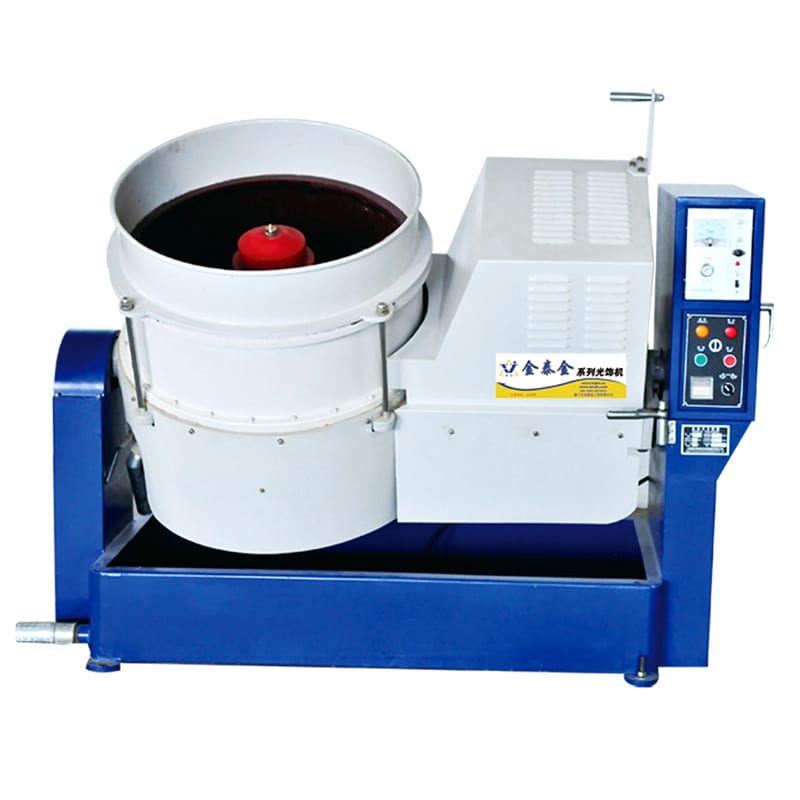
Unlike a vibratory bowl that shakes the entire tub on springs, a disc finishing machine keeps the cylindrical outer wall stationary while spinning a dished polyurethane rotor plate at the bottom.
Toroidal Vortex Physics vs. Vibratory Bowl Roll
As the bottom disc spins, centrifugal force throws media and parts outward against the stationary polyurethane cylinder wall. Forced upward along the outer wall and then curling back inward toward the center, the charge forms a continuous, high-velocity toroidal roll. Parts experience concentrated sliding pressure against media bodies rather than gentle gravity-assisted vibration.
Why Cycle Times Drop Dramatically on Compact Parts
Higher relative velocity between media and metal increases shear force per second of contact. Hardened stainless steel fasteners, coin blanks, sintered metal gears, and precision medical clips that require long shifts in a conventional rotary barrel often reach target edge radiusing in a fraction of that time inside a centrifugal disc unit.
Stationary Wall vs. Rotating Spinner Disc Gap
Every wet centrifugal disc chamber relies on a narrow circular gap between the spinning bottom disc and the stationary cylindrical drum wall. Water and fine abraded slurry flush continuously through that gap while keeping full-size media and workpieces inside the chamber. Managing that gap is the single most critical maintenance discipline in high-energy tumbling.
| Chamber Platform | Energy Transfer Mechanism | Best Workpiece Profile | Primary Risk if Misapplied |
|---|---|---|---|
| Centrifugal Disc Machine | High-speed spinning bottom disc + stationary wall | Small, rigid, high-volume metal parts | Thin stampings wedging into rotor gap; heavy part collision |
| Vibratory Bowl | Spring-mounted eccentric motor vibration | Medium-to-large parts, continuous inspection | Slower cut on hardened alloy edges |
| Octagonal Rotary Barrel | Gravity lift-and-cascade drum rotation | Heavy forgings, low-cost batch tumbling, dry plastics | Slowest cycle speed; closed-slurry rinsing |
| Drag Finisher | Rotating planetary spindles in stationary media | Heavy, high-value gears, blades, implants | Higher fixture cost per part family |
[DESIGN: Four-panel comparison showing centrifugal disc vortex motion, vibratory bowl roll, rotary barrel cascade, and drag finishing spindles]
Rotor Gap Control, Seal Rings, and Media Sizing
More disc-finishing downtime comes from jammed rotor gaps and worn ceramic seal rings than from motor or inverter faults.

Zero-Gap vs. Flushed-Gap Designs
Industrial centrifugal disc finishers use precision-machined polyurethane or ceramic-tipped gap rings fed by clean pressurized flush water. That continuous water curtain lubricates the perimeter seal, cools the polyurethane rotor, and prevents fine abrasive grit from grinding the gap wider over time.
Why Undersized Media Chips and Thin Stampings Jam the Gap
If ceramic triangles or plastic cones wear down until broken slivers approach the gap width, fragments wedge between the spinning disc and stationary wall—scoring the polyurethane liner, stalling the drive, or even snapping thin metal stampings caught edge-first in the seam.
Sizing Media Safely Above Gap Clearance
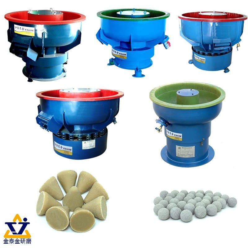
Always choose preformed ceramic or resin-bonded plastic shapes comfortably larger than the rotor gap, and screen out worn undersize media on a scheduled deck check before pebbles shrink near gap width. Never run fine magnetic pins or loose blasting grit inside a standard gap-ring disc finisher.
Checking Gap Wear Before Thin Parts Enter the Bowl
As polyurethane liners wear over months of high-energy running, the perimeter gap slowly widens. Inspect gap uniformity around the full circumference on a regular preventive schedule—especially before loading thin flat washers, razor-thin shims, or delicate watch links.
Matching Media and Chemistry to High-Energy Disc Velocity
Because a disc finishing machine hits media harder than a vibratory bowl, weak or brittle stones break down too fast inside the vortex.

High-Density Ceramic and Alumina Media for Hard Steel and Titanium
Stainless steel, alloy steel, and titanium parts run cleanly in dense preformed ceramic shapes with LC10 deburring compound. Higher bond strength resists shattering under centrifugal acceleration while cutting tough CNC burrs and heat-treat skin rapidly. Compare media families in our tumbler media selection matrix and glass bead vs. aluminum oxide media guide.
Resin-Bonded Plastic Media for Aluminum, Brass, and Zinc
Soft non-ferrous parts—such as aluminum housings, brass coin blanks, and zinc hardware—require lighter resin-bonded plastic cones paired with lower disc speeds. Running heavy ceramic at full RPM inside a centrifugal disc bruises soft aluminum edges into severe "orange peel" texture.
High-Alumina Porcelain Spheres for Rapid Burnishing
Once Stage 1 deburring erases machining ridges, switching rinsed parts into smooth high-alumina porcelain spheres with JTJ50 or JTS5 compound delivers bright, low-roughness burnishing cleanly without shattering. See our superfinishing and Ra reduction guide for multi-stage roughness progression.
Flow-Through Compound Dosing and Drain Hygiene
High-energy cutting generates metal fines rapidly. Keep continuous fresh water and metered liquid compound flowing through the chamber so suspended aluminum, brass, or steel slurry flushes straight out the gap drain rather than turning into thick gray paste inside the vortex.

Part Size, Weight, and Fragility Limits in Disc Finishers
Knowing when not to use high-energy tumbling prevents expensive scrap batches on delicate or oversized hardware.

Ideal Workpiece Envelope: Small, Rigid, Compact Parts
Centrifugal disc finishers shine on compact parts whose largest dimension stays small relative to the rotor diameter and wall height—such as coin blanks, small bevel gears, surgical forceps tips, stamped brackets, brass fittings, and jewelry castings.
Why Heavy Parts Bruise Each Other in High-Energy Vortexes
If heavy steel shafts, thick valve bodies, or massive castings are loaded together into a high-speed centrifugal disc, centrifugal energy slams parts together along the outer wall, leaving crescent nicks on threads and sealing faces. Heavy, high-value parts belong in divided vibratory troughs or drag finishing spindles instead.
Thin Flat Stampings and Spring Tangling Risks
Paper-thin washers and long open-coil springs either float toward the center, tangle into tight birds' nests under vortex spin, or slip into the perimeter gap. Thin flat stampings often finish safer in gentle vibratory bowls or magnetic tumblers.
Adjusting Variable-Frequency Speed for Delicate vs. Tough Alloys
Modern industrial disc finishers pair variable-frequency drive (VFD) speed control with programmable timers. Running higher rotor speeds maximizes burr removal on hardened steel; dialing speed back softens the vortex cushion for delicate brass, copper, or thin-walled aluminum.
| Workpiece Type | Centrifugal Disc Suitability | Recommended Alternative if Unsuitable |
|---|---|---|
| Coin blanks, small gears, fasteners | Excellent (fast, uniform vortex) | — |
| Thin flat shims & delicate springs | Poor (gap-jam & tangling risk) | Vibratory bowl or magnetic tumbler |
| Heavy valve bodies & crankshafts | Poor (severe collision bruising) | Divided vibratory trough or drag finisher |
| Machined acrylic & soft eyewear | Poor (too aggressive / wet heat) | Dry double-deck rotary barrel + organic media |
[DESIGN: Four-stage centrifugal disc workflow: load media/parts, run VFD high-energy cycle, separate/rinse, and spin-dry]
Post-Cycle Separation, Rinsing, and Drying
High-energy speed means nothing if operators spend twenty minutes picking parts out of media by hand.

Integrated Discharge and Screen Separation
Industrial disc finishers tilt or discharge directly onto a vibratory screen deck, dropping media cleanly into a return hopper while conveying parts straight into rinse baskets. Automated separation keeps batch turnaround tight across multi-shift production. Adding a polyurethane coating on the screen deck prevents newly radiused edges from nicking as parts travel off the separator.
Immediate Clean-Water Flushing Against Slurry Drying
Parts exit a high-energy disc covered in fine metal-bearing foam. Flush loads immediately in clean water before fine slurry dries inside blind bores or thread roots. On carbon steel or alloy-steel parts, include a rust-inhibiting rinse right after flushing so bare edges do not oxidize while waiting for the dryer; see our mild and carbon steel finishing guide for rust-prevention staging.
Centrifugal Spin-Drying for Spot-Free Bright Hardware
Transfer rinsed hardware straight into a heated centrifugal spin dryer to strip trapped droplets from recesses and threads within seconds. For decorative brass or stainless hardware requiring zero water-spot rings, add a brief dry wipe in warm corncob media.
Maintaining Consistent Water Pressure at the Perimeter Gap
The perimeter seal between the rotating disc and stationary drum wall depends on clean, steady flush water. If plant water pressure drops when neighboring wash stations open, abrasive grit enters the gap seam and accelerates liner wear. Install a dedicated pressure regulator and inline strainer on the disc water feed so seal lubrication stays uniform across every shift.
Comparing High-Energy Disc vs. Multi-Stage Vibratory Throughput
High-mix shops often wonder whether one large vibratory bowl or one compact disc finishing machine handles daily volume better. A centrifugal disc unit finishes small, tough parts rapidly in smaller floor space, whereas a rotary barrel tumbler or large vibratory bowl accommodates oversized brackets and continuous inspection. Many busy cells run both: a centrifugal disc for small high-hardness hardware and a vibratory bowl for larger stampings.
Inspecting Rotor Dish Contour and Liner Thickness
Over hundreds of production hours, abrasive ceramic media gradually wears the dished contour of the polyurethane bottom rotor and the lower band of the stationary wall. Inspect rotor profile and liner thickness during scheduled maintenance so worn-thin zones are relined before media exposes the steel backing plate. Catching liner wear early turns a simple relining job into planned downtime rather than an emergency rotor replacement.
Four Common Centrifugal Disc Failures and How to Diagnose Them
Failure Mode 1: Thin Parts Caught or Mangled in the Rotor Gap
Flat washers, watch links, or stamped tabs emerge bent, sheared, or jammed around the disc perimeter.
Diagnostic rule: If thin parts catch in the perimeter seam, either the rotor gap has worn wider than the part thickness or the parts are too thin for a gap-ring disc—inspect and reset gap clearance, or move thin flat stampings to a gap-free vibratory bowl.
Failure Mode 2: Overheated Chamber and Swollen Polyurethane Liner
The chamber runs hot, flush water slows to a trickle, and polyurethane walls feel soft or gummy.
Diagnostic rule: If chamber temperature spikes mid-cycle, flush water supply to the gap seal is clogged or pressure is too low—clear the water line immediately and never run a wet centrifugal disc dry.
Failure Mode 3: Severe Edge Bruising on Soft Brass or Aluminum
Corners look hammered and flat faces show micro-dimples.
Diagnostic rule: If soft non-ferrous parts show dimpling rather than smooth cutting, rotor RPM is too high or ceramic media is too heavy—reduce VFD speed, switch to resin-bonded plastic cones, and raise the media-to-part ratio.
Failure Mode 4: Rapid Media Wear and Dark Muddy Discharge
Media shrinks rapidly and water drains dark gray with thick grit.
Diagnostic rule: If media consumes abnormally fast, incoming parts carry heavy sharp laser slag or the media bond is too soft for the alloy—upgrade to high-density preformed ceramic and verify steady LC10 flow-through.
| Symptom Observed | Likely Root Cause | Immediate Fix |
|---|---|---|
| Bent/jammed thin parts | Worn rotor gap or part thinner than gap | Reset/replace gap ring or move to vibratory bowl |
| Hot bowl & swollen liner | Blocked gap-seal flush water | Restore clean pressurized flush water; never run dry |
| Dimpled brass/aluminum edges | High RPM + heavy ceramic media | Lower VFD speed; switch to plastic cones |
| Fast media breakdown | Soft media on sharp steel/slag | Upgrade to dense preformed ceramic + steady LC10 |
[DESIGN: Troubleshooting matrix linking gap jams, liner heat, edge bruising, and fast media wear to VFD and gap fixes]
Honest Capability Boundaries and Production Standards
What a Disc Finishing Machine Can and Cannot Do
A disc finishing machine delivers unmatched cycle speed for compact metal deburring, edge radiusing, and multi-stage smoothing on small-to-medium parts. However, centrifugal disc finishers cannot safely handle oversized structural frames, long shafts, thin delicate shims thinner than seal-gap clearances, or dry organic polishing of clear acrylic. For dry acrylic finishing, see our acrylic polish guide. Matching machine physics to part envelope prevents costly trial failures.
Settling Fine Slurry Before Drain Reuse
High-energy centrifugal disc units generate dense ceramic and metallic sludge rapidly during heavy stainless or alloy-steel deburring. Routing gap-drain discharge through a multi-stage settling tank keeps abrasive mud from clogging shop drains and lets clean clarified overflow stay separate from spent ceramic cake.
Training Operators on Gap Checks and Safe Loading
Before starting each shift on a disc finishing machine, operators should follow a three-point check: verify clean pressurized flush water reaches the gap seal, confirm media level sits cleanly within the working zone, and inspect incoming stampings for bent tabs or thin shims that could snag in the perimeter seam. Five minutes of pre-shift inspection prevents hours of jammed-gap downtime.
Comparing Wet Centrifugal Discs vs. Dry Magnetic Polishers
Some buyers confuse high-energy centrifugal discs with magnetic tumblers because both finish small parts rapidly. A centrifugal disc uses heavy ceramic or plastic media to cut burrs and radius sharp edges aggressively, whereas a magnetic tumbler uses tiny stainless pins to scrub inside blind bores and delicate recesses without altering outer edge tolerances. Many precision cells run both platforms sequentially.
What We Supply and What We Do Not Supply
At Xiamen Jin Tai Jin Grinding Technology Co.,Ltd. (brand: Jings Polish), our workshop roots date back to 1996 and our company was formally established in 2009, delivering over 200,000+ sets of grinding and polishing solutions worldwide. Across our catalogue, we manufacture 21 machine platforms backed by 24 granted Chinese IP rights (1 invention patent, 15 utility model patents, and 8 design patents), under ISO 9001 certification 00726Q01571R001 (valid 2026-06-03 to 2029-06-02) and CE certifications M.2023.206.C88121 (Vertical, 8 models) and M.2023.206.C88120 (Horizontal, 13 models), valid until 2028-07-24.
To keep boundaries clear: we supply industrial centrifugal disc finishers, vibratory bowls, divided troughs, drag finishers, octagonal rotary barrels, magnetic tumblers, heated centrifugal spin dryers, tumbling media, and liquid compounds (LC10, MC8, JTJ50, JTS5); we do NOT supply hobby tumblers, air-blast cabinets, handheld grinders, electroplating lines, or contract job-shop tumbling services.

Honest Lead Times and Remote Engineering Review
Standard machines ship in 25–35 days, while custom-configured disc lines and automated separation cells require 45–60 days. Because part thickness, alloy hardness, and hourly throughput determine whether a centrifugal disc or vibratory bowl is safer, we do not promise free sample trials by mail or guarantee cycle times before inspecting your workpiece—send clear photos of your parts, minimum wall/edge thickness, and target finish via our custom polishing solution page for an engineering assessment. Sharing close-up photos beside a scale or caliper lets our engineering team verify rotor gap safety, match media geometry, and size motor torque accurately on the first reply.
Upgrading From Vibratory Bowls to Centrifugal Disc Cells
When growing shops hit capacity limits on small hardened steel fasteners, precision clips, or coin blanks, adding another slow vibratory bowl consumes valuable floor space without cutting per-batch cycle time. Introducing a single high-energy centrifugal disc finisher alongside your existing vibratory separator and heated centrifugal spin dryer multiplies hourly small-part output while keeping large brackets and delicate stampings on the vibratory line.
Frequently Asked Questions
How much faster is a centrifugal disc finishing machine than a vibratory bowl?
Because centrifugal disc rotation drives media in a high-speed toroidal vortex rather than relying on gravity-assisted vibration, cycle times on compact hardened steel, stainless, and brass parts are substantially shorter than standard vibratory bowls—especially for heavy burr removal and edge radiusing.
Can thin stamped washers or flat shims run in a disc finishing machine?
Only if the minimum part thickness is safely above the rotor-to-wall gap clearance and parts will not flex into the seam. Very thin stampings risk jamming in the perimeter gap and usually run safer in a gap-free vibratory bowl.
What causes a centrifugal disc liner to overheat?
Running without sufficient pressurized flush water through the perimeter gap seal—or letting fine slurry clog the water feed—causes friction heat to build rapidly on the polyurethane rotor and stationary drum wall.
Should I use ceramic or plastic media in a high-energy disc finisher?
Use high-density preformed ceramic media for stainless steel, carbon steel, and titanium deburring, and lighter resin-bonded plastic cones at reduced VFD speed for aluminum, brass, and zinc alloys to avoid edge bruising.
How do I keep small parts from colliding inside a high-energy disc vortex?
Maintain a generous media-to-part volume ratio, dial back VFD rotor speed for heavier parts, or move heavy precision components to a divided trough or planetary drag finisher.
What details should I send before requesting a quote for a disc finishing machine?
Send clear photos of your parts next to a ruler showing minimum thickness and slot widths, along with alloy grade, part weight, and hourly batch target. Our engineers can confirm gap compatibility and size the right machine from photos and drawings.
[DESIGN: Annotated buyer enquiry checklist showing part thickness photos, alloy grade, gap clearance notes, and hourly volume]
 +86-592-2381506


 IPv6 network supported